 Web Front-end
 H5 Tutorial
 Detailed introduction to the application of HTML5 technology in new energy fields such as wind power and photovoltaics (picture)
Detailed introduction to the application of HTML5 technology in new energy fields such as wind power and photovoltaics (picture)
With the rise of a new round of industrial revolution, addressing climate change has increasingly become a global consensus, and energy technology is becoming the driving force to lead the transformation of the energy industry and achieve innovation-driven development. From the world to China, the new energy industry represented by wind energy and photovoltaic power generation has developed rapidly. The integration of renewable energy power generation and modern power grids has become the core of the world's sustainable energy transformation. Power generation technology continues to follow the path of large-scale, high efficiency and low power generation. Costs continue to improve, and China has ranked first in the world in terms of cumulative installed capacity and newly installed capacity in the fields of wind energy and photovoltaic power generation.
Compared with the stable and controllable production methods of traditional energy, wind energy and solar energy are inherently unpredictable and depend on the weather to a large extent. Therefore, building a system that integrates the Internet of Things, big data, The new energy equipment management platform integrated with cloud computing improves the "energy availability" and "time availability" of the equipment, becoming the key to upgrading and transforming the operation management methods of the enterprise itself and even the entire new energy industry. It is indispensable. is an important part of front-end big data visualization.
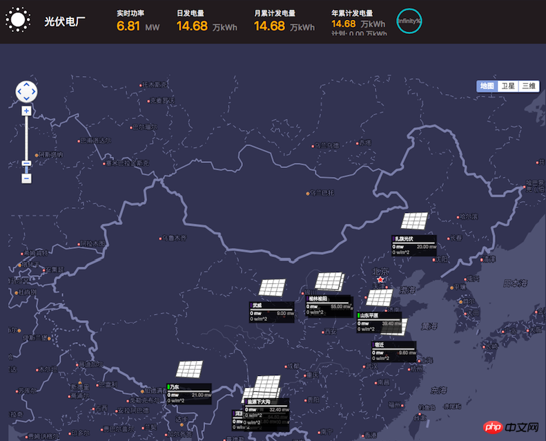
The following is a screenshot of the Web SCADA photovoltaic power station intelligent management solution system implemented by Zhichuang Energy Company many years ago based on HT for Web technology:
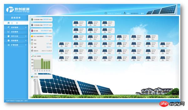
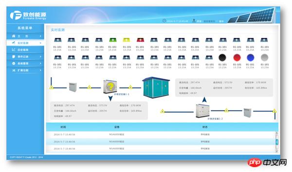
#HTML5 based on HT for Web In addition to its application in traditional telecommunications, electric power and industrial control fields (see "Web SCADA Industrial Control Based on HT for Web" "Mobile Application"), has now been widely used in new energy fields such as wind power and photovoltaics. HT for Web based on Web technology is naturally the preferred solution for PaaS and SaaS cloud platform services for IoT monitoring. Here we will be based on one of the first domestic Using the Azure IoT suite on the Microsoft Smart Cloud and integrating the Tupu software HT for Web front-end graphical interface component Middleware, we successfully created a photovoltaic monitoring interface for the Power+ IoT monitoring cloud big data platform as an example, for everyone Introducing this system front-end technology that has been applied to more than 1,000 wind turbines and more than 5,000 photovoltaic inverters and combiner boxes across the country.
The final rendering effect of the page we will introduce in detail is as follows, use the example in the HT for Web official website example center to experience it.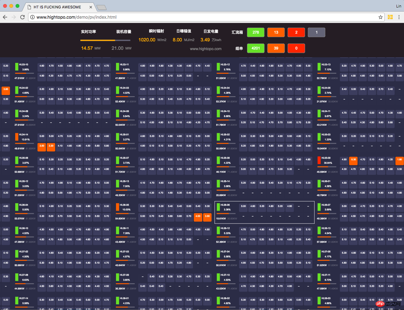


These two data values are hard-coded in the demo, but in actual operation, the data is transmitted through the background. In recent years, more and more real-time monitoring systems based on HTML5 have Using the WebSocket solution, real-time data acquisition has been achieved, and the customer in this case is no exception. As mentioned earlier, they adopted the Azure IoT suite of Microsoft Smart Cloud, so they adopted .NET-based ASP.NETSignalR is naturally the WebSocket framework solution they adopted.
function createDatas() {
    json = JSON.parse(basicData);
    json.result.forEach(function(data) {        var node = new ht.Node();
        node.setImage('symbols/enjoy/pv/pv-box.json');
        node.s({            'select.color': 'white',            '2d.selectable': false
        });
        node.a({
            deviceName: data.deviceName,
            capacity: data.capacity + 'KW',
            raw_capacity: data.capacity
        });
        node.setTag(data.deviceCode);
        graphView.getDataModel().add(node);
    });
}When the page opens, the system first constructs hundreds of combiner box primitives based on the basicData information in the CreateData function, and passes node.setImage('symbols /enjoy/pv/pv-box.json'); Set the graphics element to the combiner box vector we constructed, and then use the simple extended layout algorithm in the example to matrix layout hundreds of combiner box devices. Of course, you will encounter You can use HT's automatic layout to arrange complex network topology diagrams:
One thing to note here is that we set the tag of each graphic element through node.setTag(data.deviceCode) when building the graphic elements. Tag tag, this is very important. This is used to quickly find the corresponding graphic element and prepare for data update.
function fillDatas() {
var hlx_state_0 = hlx_state_1 = hlx_state_2 = hlx_state_3 = 0;
var zc_state_1 = zc_state_2 = zc_state_3 = 0;

    json = JSON.parse(realTimeData);
    json.result.wtrtDatas.forEach(function(data) {
        var comboxRTDto = data.comboxRTDto;
        var node = graphView.getDataModel().getDataByTag(comboxRTDto.deviceCode);
        if (node) {
            var hlxState = comboxRTDto.pvDeviceStCode;
            node.a({
                hlxState: hlxStateMap[hlxState],
                discreteRate: comboxRTDto.discreteRate + '%',
                outputPower: comboxRTDto.outputPower + 'KW',
                percentage:  comboxRTDto.outputPower / node.a('raw_capacity')
            });
        }
    });
}After the above work is completed, the interface can already display all photovoltaic combiner box equipment, but the parameter information displayed by each equipment is the initialization set when we build the vector icon. It is not a real real-time running value, so we need to update the data of the graphics element based on the data pushed in real time from the background. In the above fillData function, we parse the realTimeData data, and then traverse the data of each combiner box, through dataModel.getDataByTag(deviceCode ) Find the corresponding primitive and set the corresponding attr attributes. Since these attributes have been bound to the corresponding graphic parameters during vector design, when all the data is set, each corresponding combiner box on the topology map can automatically Real real-time data is displayed.
In this example, we only updated the real-time data once, but a normal system will poll for a few seconds through AJAX, or use WebSocket to push the data from the background to the front-end in real time when there are changes, and then call fillDatas multiple times. function to update the data. In addition, the content of this interface scene is dynamically constructed after the first basicData query. If you already have the JSON data serialized by the topology map, you only need to deserialize it to build the topology map scene. Serialization and deserialization
After completing the above, we have only completed half of the work. Remember that we still have a summary and filtering panel in the upper part:

When I first started looking at this design draft, I naturally thought that the panel and operation buttons could be done using the Panel component of HT for Web: www.hightopo.com/guide/guide/plugin/form/ ht-form-guide.html, but then I thought about the fact that the style of general components is relatively fixed, and even if the effect is customized, it is difficult to cope with the changing needs. I suddenly thought that we can still use the GraphView topology component of HT for Web to do it. In this matter, the text above is nothing more than ht.Text primitives, Progress bar is a Node node with a shape type of rect, and the filter control button is actually just a bunch of Node primitives, but we set Different background colors, center the label label, and change the element selection effect from the border to the shadow selection effect, and you are done. Moreover, since it is a topological map layout, users can change the layout position or interface style regardless of changes in requirements. It can be easily dragged and dropped, and new style parameters can be set to meet changing business display needs
function createHeader() {
    header = new ht.graph.GraphView();
    ht.Default.xhrLoad('displays/enjoy/pv/pv-header.json', function(json) {
        header.getDataModel().deserialize(json);
        header.getDataModel().setBackground(undefined);
        createDatas();
        fillDatas();
        layoutDatas();
    });
    header.setInteractors(null);
    var handleClick = function(e) {
    if (!graphView.getView().contains(e.target)) {
    var data = header.getDataAt(e);
            header.sm().ss(data);
        }
    };
    document.body.addEventListener('mousedown', handleClick, false);
    document.body.addEventListener('touchstart', handleClick, false);
}汇总部分就是有以上 createHeader 函数搞定,注意这里我们通过 ht.Default.xhrLoad('displays/enjoy/pv/pv-header.json 直接加载已经序列化好的拓扑图信息,然后由于该汇总面板唯一需要的交互就是点击选中分类按钮进行过滤,于是我们通过 header.setInteractors(null); 直接关闭了所有 HT for Web 的默认交互,然后通过添加 mousedown 和 touchstart 的原生 HTML 监听事件自定义交互逻辑,这里只需要通过 header.getDataAt(event) 传入不管是 touch 还是 mouse 事件,HT 自动回返回当前操作点下的图元,后续过滤已经动画的逻辑比较简单,这里就不展开说明了,有兴趣的可以改造成更带感的过滤动画布局效果,可参考《透过WebGL 3D看动画Easing函数本质》一文了解 HT for Web 的各种预制的动画功能。
这里我们仅演示了光伏的一个页面效果,风电的风机也可以采用类似的方式呈现,这个上万个矢量风机实时转动的 HTML5 性能效果,也可以结合例如百度地图、OpenLayers 或 GoogleMap 等地图方案呈现风机或光伏监控画面:
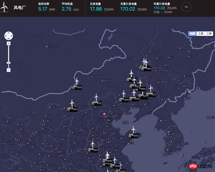
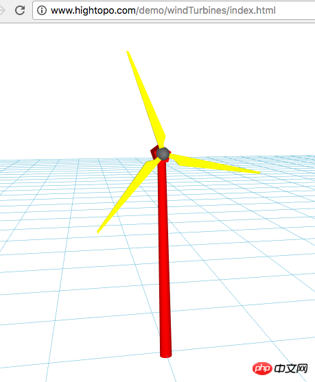
对于看腻了 2D 矢量风机的,这个采用 HT for Web 实现的 3D 可旋转风机 HTML5 的代码也就寥寥几十行,今天篇幅有限先不展开介绍了,大家就先玩玩 demo 。
The above is the detailed content of Detailed introduction to the application of HTML5 technology in new energy fields such as wind power and photovoltaics (picture). For more information, please follow other related articles on the PHP Chinese website!

Hot AI Tools

Undresser.AI Undress
AI-powered app for creating realistic nude photos

AI Clothes Remover
Online AI tool for removing clothes from photos.

Undress AI Tool
Undress images for free

Clothoff.io
AI clothes remover

AI Hentai Generator
Generate AI Hentai for free.

Hot Article

Hot Tools

Notepad++7.3.1
Easy-to-use and free code editor

SublimeText3 Chinese version
Chinese version, very easy to use

Zend Studio 13.0.1
Powerful PHP integrated development environment

Dreamweaver CS6
Visual web development tools

SublimeText3 Mac version
God-level code editing software (SublimeText3)

Hot Topics
 1385
1385
 52
52
 Table Border in HTML
Sep 04, 2024 pm 04:49 PM
Guide to Table Border in HTML. Here we discuss multiple ways for defining table-border with examples of the Table Border in HTML.
 HTML margin-left
Sep 04, 2024 pm 04:48 PM
Guide to HTML margin-left. Here we discuss a brief overview on HTML margin-left and its Examples along with its Code Implementation.
 Nested Table in HTML
Sep 04, 2024 pm 04:49 PM
This is a guide to Nested Table in HTML. Here we discuss how to create a table within the table along with the respective examples.
 HTML Table Layout
Sep 04, 2024 pm 04:54 PM
Guide to HTML Table Layout. Here we discuss the Values of HTML Table Layout along with the examples and outputs n detail.
 HTML Input Placeholder
Sep 04, 2024 pm 04:54 PM
Guide to HTML Input Placeholder. Here we discuss the Examples of HTML Input Placeholder along with the codes and outputs.
 HTML Ordered List
Sep 04, 2024 pm 04:43 PM
Guide to the HTML Ordered List. Here we also discuss introduction of HTML Ordered list and types along with their example respectively
 Moving Text in HTML
Sep 04, 2024 pm 04:45 PM
Guide to Moving Text in HTML. Here we discuss an introduction, how marquee tag work with syntax and examples to implement.
 HTML onclick Button
Sep 04, 2024 pm 04:49 PM
Guide to HTML onclick Button. Here we discuss their introduction, working, examples and onclick Event in various events respectively.


