Graphical introduction to tcp, udp and ip protocols in Java
This article mainly introduces the relevant information of tcp, udp, and ip protocol analysis in detail. It has certain reference value. Interested friends can refer to it
In the early days of the Internet, the host The interconnection between them uses the NCP protocol. This protocol itself has many defects, such as: it cannot interconnect different hosts, it cannot interconnect different operating systems, and it has no error correction function. In order to improve this shortcoming, Daniel came up with the TCP/IP protocol. Almost all operating systems now implement the TCP/IP protocol stack.
The TCP/IP protocol stack is mainly divided into four layers: application layer, transport layer, network layer, and data link layer. Each layer has a corresponding protocol, as shown below
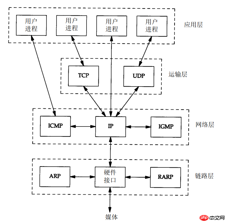
The so-called protocol is a format for data transmission between both parties. There are many protocols used throughout the network, and fortunately each protocol has an RFC document. Here we only do an analysis of the IP, TCP, and UDP protocol headers.
First, let’s take a look at the format of an Ethernet data packet in the network:

In the Linux operating system, When we want to send data, we only need to prepare the data in the upper layer, and then submit it to the kernel protocol stack, and the kernel protocol stack automatically adds the corresponding protocol header. Let's take a look at the specific content of the protocol header added at each layer.
1. TCP protocol
TCP protocol is connection-oriented and ensures high reliability (no data loss, no data disorder, no data error) , no duplicate data arrival) transport layer protocol.
1.TCP header analysis
Let’s first analyze the format of the TCP header and the meaning of each field:
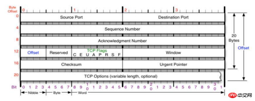
(1) Port number [16bit]
We know that the network implements inter-process communication between different hosts. In an operating system, there are many processes. When data arrives, which process should be submitted to it for processing? This requires the use of port numbers. In the TCP header, there are source port number (Source Port) and destination port number (Destination Port). The source port number identifies the process of the sending host, and the destination port number identifies the process of the receiving host.
(2) Sequence number [32bit]
The sequence number is divided into sending sequence number (Sequence Number) and confirmation sequence number (Acknowledgment Number).
Sending sequence number: used to identify the data byte stream sent from the TCP source to the TCP destination. It indicates the sequence number of the first data byte in this message segment. If you think of a byte stream as a one-way flow between two applications, TCP counts each byte with a sequence number. The serial number is a 32-bit unsigned number. The serial number starts from 0 after reaching 2 32-1. When a new connection is established, the SYN flag changes to 1 and the sequence number field contains the initial sequence number ISN (Initial Sequence Number) selected by this host for the connection.
Confirmation sequence number: Contains the next sequence number that the end sending the confirmation expects to receive. Therefore, the confirmation sequence number should be the last successfully received data byte sequence number plus 1. The confirmation sequence number field is valid only when the ACK flag is 1. TCP provides full-duplex services to the application layer, which means that data can be transmitted independently in both directions. Therefore, each end of the connection must maintain the sequence number of transmitted data in each direction.
(3) Offset [4bit]
The offset here actually refers to the length of the TCP header, which is used to indicate the length of the 32-bit word in the TCP header. Number, through which you can know where the user data of a TCP packet starts. This field occupies 4 bits. If the value of 4 bits is 0101, it means that the TCP header length is 5 * 4 = 20 bytes. So the maximum TCP header length is 15 * 4 = 60 bytes. However, there are no optional fields and the normal length is 20 bytes.
(4)Reserved [6bit]
is not currently used, its value is 0
(5) Flag [6bit ]
There are 6 flag bits in the TCP header. Multiple of them can be set to 1 at the same time.
URG The urgent pointer is valid
ACK Confirm that the sequence number is valid
PSH Indicates that the receiver should hand this segment to the application layer as soon as possible without using it Waiting for the buffer to be filled
RST generally means disconnecting a connection
For example: a TCP client initiates a connection to a server that does not have a listening port, and Wirshark captures the packet as follows

You can see that host:192.168.63.134 initiates a connection request to host:192.168.63.132, but host:192.168.63.132 is not on the server side listening to the corresponding port. This When
host: 192.168.63.132 sends a TCP packet with RST set to disconnect.
SYN The synchronization sequence number is used to initiate a connection
FIN The sender completes the sending task (i.e. disconnects the connection)
(6)Window size (window)[16bit]
The size of the window, indicating the maximum number of bytes that the source method can accept. .
(7) Checksum [16bit]
The checksum covers the entire TCP message segment: TCP header and TCP data. This is a mandatory field that must be calculated and stored by the originator and verified by the receiver.
(8) Emergency pointer [16bit]
The emergency pointer is valid only when the URG flag is set to 1. The urgent pointer is a positive offset, added to the value in the sequence number field, to represent the sequence number of the last byte of urgent data. TCP's emergency mode is a way for the sender to send urgent data to the other end.
(9)TCP option
is optional, we will take a look at it when capturing packets later
2. Key details
(1) Three-way handshake to establish connection
a. The requesting end (usually called the client) sends a SYN segment to indicate the client The port of the server you intend to connect to, and the initial sequence number (ISN, in this case 1415531521). This SYN segment is message segment 1.
b. The server sends back a SYN segment (segment 2) containing the server's initial sequence number as a response. At the same time, the confirmation sequence number is set to the customer's ISN plus 1 to confirm the customer's SYN message segment. A SYN will occupy a sequence number
c. The client must set the confirmation sequence number to the server's ISN plus 1 to confirm the server's SYN segment (segment 3)
These three segments complete the connection of establishment. This process is also called a three-way handshake
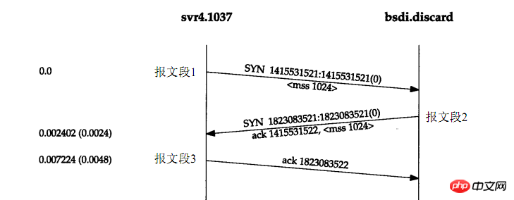
Use wirshark to capture the packet as follows:

You can see that the three-way handshake determines the sequence number of the packets between the two parties, the maximum received data size (window), and the MSS (Maximum Segment Size).
MSS = MTU - IP header - TCP header. MTU represents the maximum transmission unit. We will talk about it when analyzing the IP header. It is generally 1500 bytes. Both the IP header and the TCP header are 20 bytes with optional options. In this case MSS=1500 - 20 -20 = 1460.
MSS limits the size of data carried by TCP packets. It means that when the application layer submits data to the transport layer for transmission through the TCP protocol, if the application layer data > MSS, it must be segmented. , divided into multiple segments and sent one by one.
For example: the application layer submits 4096 bytes of data to the transport layer at one time. At this time, the effect of packet capture through wirshark is as follows:

The first three times are the three-way handshake process, and the next three times are the process of transmitting data. Since the data size is 4096 bytes, it takes three times to transmit (1448 + 1448 + 1200). Careful people will ask why the maximum data size transmitted each time is not 1460 bytes? Because TCP here carries optional options, TCP header length = 20 + 12 (optional option size) = 32 bytes. The maximum data that can be transmitted in this way is: 1500 - 20 - 32 = 1448 bytes.
(2) Wave four times to disconnect
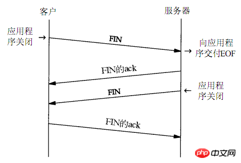
a. Current network communication is based on sockets. When the client closes its own socket , the kernel protocol stack will automatically send a packet with FIN set to the server, requesting to disconnect. We call the party that initiates the disconnection request first as the active disconnecting party.
b. After the server receives the client's FIN disconnect request, the kernel protocol stack will immediately send an ACK packet as a response, indicating that the client's request has been received.
c. After the server has been running for a period of time, it shuts down itself. socket. At this time, the kernel protocol stack will send a FIN set packet to the client, requesting to disconnect
d. After the client receives the FIN disconnect request from the server, it will send an ACK in response, indicating The request from the server has been received

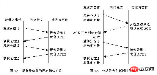
TCP uses a technology called "positive acknowledgment with retransmission" as the basis for providing reliable data transmission services. This technology requires the receiver to send confirmation information ACK back to the source station after receiving the data. The sender keeps a record of each packet sent and waits for confirmation before sending the next packet. The sender also starts a timer while sending the packet, and resends the packet just sent when the timer expires but the acknowledgment information has not arrived. Figure 3-5 shows the data transmission situation of the positive acknowledgment protocol with retransmission function, and Figure 3-6 shows the timeout and retransmission caused by packet loss. In order to avoid late acknowledgments and duplicate acknowledgments due to network delays, the protocol stipulates that the acknowledgment information contains a packet sequence number so that the receiver can correctly associate the packet with the acknowledgment.
As can be seen from Figure 3-5, although the network has the ability to conduct two-way communication at the same time, since the sending of the next packet must be postponed before receiving the confirmation information of the previous packet, the simple positive confirmation protocol A lot of valuable network bandwidth is wasted. To this end, TCP uses a sliding window mechanism to improve network throughput while solving end-to-end flow control.
(4) Sliding window technology
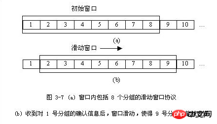
Sliding window technology is a simple positive confirmation mechanism with retransmission A more complex variant that allows the sender to send multiple packets before waiting for an acknowledgment. As shown in Figure 3-7, the sender wants to send a packet sequence. The sliding window protocol places a fixed-length window in the packet sequence, and then sends all the packets in the window; when the sender receives the When a packet's confirmation information is received, it can slide back and send the next packet; as confirmations continue to arrive, the window continues to slide back.
2. UDP protocol
The UDP protocol is also a transport layer protocol. Connection, transport layer protocols that do not guarantee reliability. Its protocol header is relatively simple, as follows:

The port number here will not be explained, it has the same meaning as the TCP port number.
Length occupies 2 bytes and identifies the length of the UDP header. Checksum: Checksum, including UDP header and data parts.
3. IP protocol
IP is the core protocol in the TCP/IP protocol suite. All TCP, UDP, ICMP and IGMP data are transmitted in IP datagram format. Its characteristics are as follows:
Unreliable (u n r e l i a b l e) means that it cannot guarantee that the IP datagram can successfully reach the destination. IP only provides the best transmission services. If an error occurs, such as a router temporarily running out of buffers, IP has a simple error handling algorithm: discard the datagram, and then send an ICMP message to the source. Any required reliability must be provided by upper layers (such as TCP).
The term connectionless (con n e c t i o n l e s s) means that IP does not maintain any state information about subsequent datagrams. Each datagram is processed independently of each other. This also means that IP datagrams can be received out of the order they were sent. If a source sends two consecutive datagrams (first A, then B) to the same sink, each datagram is routed independently, possibly taking a different route, so B may arrive before A. arrive.
1.IP header format
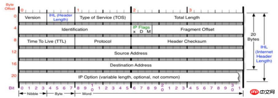
(1)The version occupies 4 bits and refers to the IP protocol Version. The IP protocol versions used by both communicating parties must be consistent. The currently widely used IP protocol version number is 4 (IPv4). Regarding IPv6, it is still in the draft stage.
(2) Header length occupies 4 digits, and the maximum representable decimal value is 15. Please note that the unit of the number represented by this field is 32-bit word length (a 32-bit word length is 4 bytes). Therefore, when the IP header length is 1111 (that is, 15 in decimal), the header length reaches 60 byte. When the length of the IP packet header is not an integer multiple of 4 bytes, it must be filled with the last padding field. Therefore, the data part always starts at an integer multiple of 4 bytes, which is more convenient when implementing the IP protocol. The disadvantage of limiting the header length to 60 bytes is that it may not be sufficient in some cases. But this is done in the hope that users will minimize overhead. The most commonly used header length is 20 bytes (that is, the header length is 0101), and no options are used at this time.
(3) Differentiated services occupy 8 bits and are used to obtain better services. This field was called service type in the old standard, but has never been used in practice. In 1998, the IETF renamed this field DS (Differentiated Services). This field only takes effect when using differentiated services.
(4) Total length The total length refers to the length of the header and data, in bytes. The total length field is 16 bits, so the maximum length of the datagram is 216-1 = 65535 bytes.
Each data link layer below the IP layer has its own frame format, which includes the maximum length of the data field in the frame format, which is called the Maximum Transfer Unit (MTU). When a datagram is encapsulated into a link layer frame, the total length of the datagram (that is, the header plus the data part) must not exceed the MTU value of the underlying data link layer.
(5)Identification (identification) occupies 16 digits. The IP software maintains a counter in memory. Each time a datagram is generated, the counter is incremented by 1 and this value is assigned to the identification field. But this "identification" is not a sequence number, because IP is a connectionless service, and there is no problem of receiving datagrams in order. When a datagram must be fragmented because its length exceeds the network's MTU, the value of this identification field is copied to the identification field of all datagrams. The same identification field value enables each fragmented datagram fragment to be correctly reassembled into the original datagram.
(6) Flag (flag) occupies 3 digits, but currently only 2 digits are meaningful.
● The lowest bit in the flag field is recorded as MF (More Fragment). MF=1 means that there will be "fragmented" datagrams later. MF=0 means that this is the last of several datagram fragments
●. The bit in the middle of the flag field is recorded as DF (Don't Fragment), which means "cannot be fragmented". Fragmentation is only allowed when DF=0.
(7) slice offset occupies 13 bits. The slice offset points out: the relative position of a certain slice in the original packet after a longer packet is fragmented. That is, where the slice begins relative to the starting point of the user data field. The slice offset is in 8-byte offset units. This means that the length of each fragment must be an integer multiple of 8 bytes (64 bits).
(8) Time to Live occupies 8 bits. The commonly used English abbreviation of the time to live field is TTL (Time To Live), which indicates the life span of the datagram in the network. This field is set by the origin of the datagram. Its purpose is to prevent undeliverable datagrams from circulating around the Internet indefinitely, thus consuming network resources in vain. The original design was to use seconds as the unit of TTL. Each time it passes through a router, the TTL is subtracted from the period of time the datagram consumes in the router. If the datagram takes less than 1 second at the router, the TTL value is decremented by 1. When the TTL value is 0, the datagram is discarded.
(9) Protocol Occupies 8 bits. The protocol field indicates which protocol is used for the data carried in this datagram, so that the IP layer of the destination host knows which processing process the data part should be handed over.
(10) The first checksum occupies 16 positions. This field only checks the header of the datagram, but not the data part. This is because every time a datagram passes through a router, the router must recalculate the header checksum (some fields, such as time-to-live, flags, fragment offsets, etc., may change). Not checking parts of the data reduces computational effort.
(11) Source IP address occupies 32 bits.
(12) Destination IP address occupies 32 bits.
2. Fragmentation explanation
Fragmentation refers to when the data to be transmitted is larger than the maximum transmission unit (MTU), it is necessary Divide it into multiple packages and send them to the other party one by one. When we talk about TCP, when it comes to MSS, many people can't distinguish them. Through the picture below, I think we can completely distinguish them. 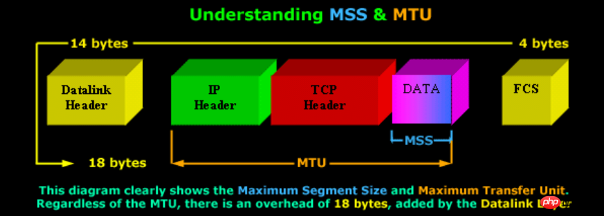
Personally, I feel that if data is transmitted through the TCP protocol, fragmentation is definitely not needed when it reaches the IP layer. Fragmentation is only required when transmitting large data through the UDP protocol.
For example: Use UDP protocol to transmit 10240 bytes of data

It can be seen, but when the data is submitted to the network layer, because the data exceeds the maximum The transmission unit is fragmented. Divide it into multiple packets and send them to the other party through the IP protocol. The maximum byte of each packet is MTU - IP header = 1500 - 20 = 1480.
4. Ethernet header


The ARP protocol obtains the corresponding MAC address through the IP address, which is called the address resolution protocol
The RARP protocol obtains the corresponding IP address through the MAC address , called the reverse address resolution protocol
The above is the detailed content of Graphical introduction to tcp, udp and ip protocols in Java. For more information, please follow other related articles on the PHP Chinese website!

Hot AI Tools

Undresser.AI Undress
AI-powered app for creating realistic nude photos

AI Clothes Remover
Online AI tool for removing clothes from photos.

Undress AI Tool
Undress images for free

Clothoff.io
AI clothes remover

AI Hentai Generator
Generate AI Hentai for free.

Hot Article

Hot Tools

Notepad++7.3.1
Easy-to-use and free code editor

SublimeText3 Chinese version
Chinese version, very easy to use

Zend Studio 13.0.1
Powerful PHP integrated development environment

Dreamweaver CS6
Visual web development tools

SublimeText3 Mac version
God-level code editing software (SublimeText3)

Hot Topics
 1376
1376
 52
52
 Square Root in Java
Aug 30, 2024 pm 04:26 PM
Guide to Square Root in Java. Here we discuss how Square Root works in Java with example and its code implementation respectively.
 Perfect Number in Java
Aug 30, 2024 pm 04:28 PM
Guide to Perfect Number in Java. Here we discuss the Definition, How to check Perfect number in Java?, examples with code implementation.
 Random Number Generator in Java
Aug 30, 2024 pm 04:27 PM
Guide to Random Number Generator in Java. Here we discuss Functions in Java with examples and two different Generators with ther examples.
 Weka in Java
Aug 30, 2024 pm 04:28 PM
Guide to Weka in Java. Here we discuss the Introduction, how to use weka java, the type of platform, and advantages with examples.
 Smith Number in Java
Aug 30, 2024 pm 04:28 PM
Guide to Smith Number in Java. Here we discuss the Definition, How to check smith number in Java? example with code implementation.
 Java Spring Interview Questions
Aug 30, 2024 pm 04:29 PM
In this article, we have kept the most asked Java Spring Interview Questions with their detailed answers. So that you can crack the interview.
 Break or return from Java 8 stream forEach?
Feb 07, 2025 pm 12:09 PM
Java 8 introduces the Stream API, providing a powerful and expressive way to process data collections. However, a common question when using Stream is: How to break or return from a forEach operation? Traditional loops allow for early interruption or return, but Stream's forEach method does not directly support this method. This article will explain the reasons and explore alternative methods for implementing premature termination in Stream processing systems. Further reading: Java Stream API improvements Understand Stream forEach The forEach method is a terminal operation that performs one operation on each element in the Stream. Its design intention is
 TimeStamp to Date in Java
Aug 30, 2024 pm 04:28 PM
Guide to TimeStamp to Date in Java. Here we also discuss the introduction and how to convert timestamp to date in java along with examples.


