This article mainly introduces you to the practical process of using Three.js to develop and implement 3D maps. The article introduces it in great detail through sample code. It has certain reference learning value for everyone to learn or use three.js. Friends who need it Let’s learn with the editor below. Hope it helps everyone.
Preface
This article mainly introduces the development foundation and basic principles of Three.js, and how to realize 3D panorama. If you want to achieve the effect of a 3D panorama on the web, in addition to panoramic images and WebGL, you also need to deal with many details. As far as I know, KrPano is currently the best foreign 3D panorama service, and many domestic 3D panorama services are using krpano tools.
I worked for a month straight some time ago and worked overtime to complete a 3D project. It can be regarded as the transition from traditional web to webgl graphics development, and there are many pitfalls. I made a summary and shared it.
Three.js
Based on the purpose of simplifying the complexity of WebGL development and reducing the difficulty of entry, mrdoob) encapsulates a lightweight JS 3D library based on the WebGL standard - Three.js .
In my opinion, Three.js has the following characteristics:
It has the complete functions required for 3D development. Basically, the effects that can be achieved using WebGL can be achieved with Three. .js can be realized more simply
The easy-to-use architecture design is relatively clear and reasonable, easy to understand, has good scalability, and the development efficiency is higher than WebGL
The open source project is open source and has a group of active contributors. It is under continuous maintenance and upgrade
Three.js makes WebGL easier to use and can achieve great 3D effects. For example:
Game hellorun
Data visualization armsglobe
1. Normal vector problem
Normals are vectors perpendicular to the surface of the object we want to illuminate. Normals represent the direction of a surface so they play a decisive role in modeling the interaction between light sources and objects. Every vertex has an associated normal vector.
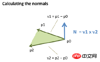
If a vertex is shared by multiple triangles, the normal vector of the shared vertex is equal to the sum of the normal vectors of the shared vertex in different triangles. N=N1+N2;
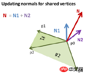
So if you do not do any processing and directly pass the points of the 3D object to BufferGeometry, then since the normal vector is synthesized, it will be colored by the fragment After interpolation, you will get this black and white effect

My processing method keeps the normal vector of the vertex unique, then you need to copy a vertex at the shared vertex , and recalculate the index. Yes, each vertex shared by multiple faces has multiple copies, and each copy has a separate normal vector, so that each face has the same color

2. Light source and surface block color
During the development process, a set of color combinations was designed. However, once there is a light source, the final color of the surface block will be mixed with the light source. Naturally the color is very different from the final design. The following is the hybrid algorithm of Lambert lighting model.

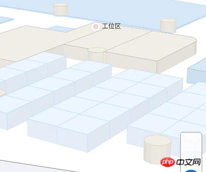
Moreover, the requirement of the product is that the top surface maintains the color of the design, and the light source change effect needs to be added to the side. When the map is operated, the color of the side needs to change according to the viewing angle. Then my way of handling it is to draw the top surface and the side surface separately (create two Mesh), use the emssive attribute of MeshLambertMaterial to set the self-illumination color on the top surface to be consistent with the design color, so there will be no lighting effect, and use Emssive and the side surface comprehensively color to apply light effects.
var material1 = new __WEBPACK_IMPORTED_MODULE_0_three__["MeshLambertMaterial"]({
 emissive: new __WEBPACK_IMPORTED_MODULE_0_three__["Color"](style.fillStyle[0], style.fillStyle[1], style.fillStyle[2]),
 side: __WEBPACK_IMPORTED_MODULE_0_three__["DoubleSide"],
 shading: __WEBPACK_IMPORTED_MODULE_0_three__["FlatShading"],
 vertexColors: __WEBPACK_IMPORTED_MODULE_0_three__["VertexColors"]
 });

 var material2 = new __WEBPACK_IMPORTED_MODULE_0_three__["MeshLambertMaterial"]({
 color: new __WEBPACK_IMPORTED_MODULE_0_three__["Color"](style.fillStyle[0] * 0.1, style.fillStyle[1] * 0.1, style.fillStyle[2] * 0.1),
 emissive: new __WEBPACK_IMPORTED_MODULE_0_three__["Color"](style.fillStyle[0] * 0.9, style.fillStyle[1] * 0.9, style.fillStyle[2] * 0.9),
 side: __WEBPACK_IMPORTED_MODULE_0_three__["DoubleSide"],
 shading: __WEBPACK_IMPORTED_MODULE_0_three__["FlatShading"],
 vertexColors: __WEBPACK_IMPORTED_MODULE_0_three__["VertexColors"]
});3. POI annotation
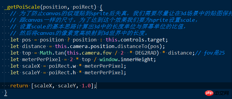
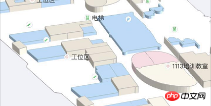
Three can use the Sprite class to create a POI that always faces the camera, and at the same time, text and pictures can be drawn on the canvas. Place the canvas as a texture map on the Sprite. But one problem here is that the canvas image will be distorted. The reason is that the scale of the sprite is not set appropriately, causing the image to be stretched or scaled and distorted.

The solution to the problem is to ensure that the zoom size in the 3D world remains consistent with the size of the canvas on the screen after a series of transformations and projection to the camera screen. This requires us to calculate the ratio of screen pixels to length units in the 3D world, and then scale the sprite to the appropriate 3D length.
4. Click picking problem
The drawing of 3D objects in webgl to the screen will go through the following stages

所以要在3D应用做点击拾取,首先要将屏幕坐标系转化成ndc坐标系,这时候得到ndc的xy坐标,由于2d屏幕并没有z值所以,屏幕点转化成3d坐标的z可以随意取值,一般取0.5(z在-1到1之间
function fromSreenToNdc(x, y, container) {
 return {
 x: x / container.offsetWidth * 2 - 1,
 y: -y / container.offsetHeight * 2 + 1,
 z: 1
 };
}
function fromNdcToScreen(x, y, container) {
 return {
 x: (x + 1) / 2 * container.offsetWidth,
 y: (1 - y) / 2 * container.offsetHeight
 };
}然后将ndc坐标转化成3D坐标: ndc = P * MV * Vec4 Vec4 = MV-1 * P -1 * ndc 这个过程在Three中的Vector3类中已经有实现:
unproject: function () {

 var matrix = new Matrix4();

 return function unproject( camera ) {

 matrix.multiplyMatrices( camera.matrixWorld, matrix.getInverse( camera.projectionMatrix ) );
 return this.applyMatrix4( matrix );

 };

}(),将得到的3d点与相机位置结合起来做一条射线,分别与场景中的物体进行碰撞检测。首先与物体的外包球进行相交性检测,与球不相交的排除,与球相交的保存进入下一步处理。将所有外包球与射线相交的物体按照距离相机远近进行排序,然后将射线与组成物体的三角形做相交性检测。求出相交物体。当然这个过程也由Three中的RayCaster做了封装,使用起来很简单:
mouse.x = ndcPos.x;
 mouse.y = ndcPos.y;

 this.raycaster.setFromCamera(mouse, camera);

 var intersects = this.raycaster.intersectObjects(this._getIntersectMeshes(floor, zoom), true);
5、性能优化
随着场景中的物体越来越多,绘制过程越来越耗时,导致手机端几乎无法使用。
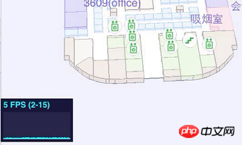
在图形学里面有个很重要的概念叫“one draw all”一次绘制,也就是说调用绘图api的次数越少,性能越高。比如canvas中的fillRect、fillText等,webgl中的drawElements、drawArrays;所以这里的解决方案是对相同样式的物体,把它们的侧面和顶面统一放到一个BufferGeometry中。这样可以大大降低绘图api的调用次数,极大的提升渲染性能。

这样解决了渲染性能问题,然而带来了另一个问题,现在是吧所有样式相同的面放在一个BufferGeometry中(我们称为样式图形),那么在面点击时候就无法单独判断出到底是哪个物体(我们称为物体图形)被选中,也就无法对这个物体进行高亮缩放处理。我的处理方式是,把所有的物体单独生成物体图形保存在内存中,做面点击的时候用这部分数据来做相交性检测。对于选中物体后的高亮缩放处理,首先把样式面中相应部分裁减掉,然后把选中的物体图形加入到场景中,对它进行缩放高亮处理。裁剪方法是,记录每个物体在样式图形中的其实索引位置,在需要裁切时候将这部分索引制零。在需要恢复的地方在把这部分索引恢复成原状。
6、面点击移动到屏幕中央
这部分也是遇到了不少坑,首先的想法是:
面中心点目前是在世界坐标系内的坐标,先用center.project(camera)得到归一化设备坐标,在根据ndc得到屏幕坐标,而后根据面中心点屏幕坐标与屏幕中心点坐标做插值,得到偏移量,在根据OribitControls中的pan方法来更新相机位置。这种方式最终以失败告终,因为相机可能做各种变换,所以屏幕坐标的偏移与3d世界坐标系中的位置关系并不是线性对应的。
最终的想法是:
我们现在想将点击面的中心点移到屏幕中心,屏幕中心的ndc坐标永远都是(0,0)我们的观察视线与近景面的焦点的ndc坐标也是0,0;也就是说我们要将面中心点作为我们的观察点(屏幕的中心永远都是相机的观察视线),这里我们可以直接将面中心所谓视线的观察点,利用lookAt方法求取相机矩阵,但如果这样简单处理后的效果就会给人感觉相机的姿态变化了,也就是会感觉并不是平移过去的,所以我们要做的是保持相机当前姿态将面中心作为相机观察点。
回想平移时我们将屏幕移动转化为相机变化的过程是知道屏幕偏移求target,这里我们要做的就是知道target反推屏幕偏移的过程。首先根据当前target与面中心求出相机的偏移向量,根据相机偏移向量求出在相机x轴和up轴的投影长度,根据投影长度就能返推出应该在屏幕上的平移量。
this.unprojectPan = function(deltaVector, moveDown) {
 // var getProjectLength()
 var element = scope.domElement === document ? scope.domElement.body : scope.domElement;

 var cxv = new Vector3(0, 0, 0).setFromMatrixColumn(scope.object.matrix, 0);// 相机x轴
 var cyv = new Vector3(0, 0, 0).setFromMatrixColumn(scope.object.matrix, 1);// 相机y轴
 // 相机轴都是单位向量
 var pxl = deltaVector.dot(cxv)/* / cxv.length()*/; // 向量在相机x轴的投影
 var pyl = deltaVector.dot(cyv)/* / cyv.length()*/; // 向量在相机y轴的投影

 // offset=dx * vector(cx) + dy * vector(cy.project(xoz).normalize)
 // offset由相机x轴方向向量+相机y轴向量在xoz平面的投影组成
 var dv = deltaVector.clone();
 dv.sub(cxv.multiplyScalar(pxl));
 pyl = dv.length();

 if ( scope.object instanceof PerspectiveCamera ) {
 // perspective

 var position = scope.object.position;
 var offset = new Vector3(0, 0, 0);
 offset.copy(position).sub(scope.target);
 var distance = offset.length();
 distance *= Math.tan(scope.object.fov / 2 * Math.PI / 180);

 // var xd = 2 * distance * deltaX / element.clientHeight;
 // var yd = 2 * distance * deltaY / element.clientHeight;
 // panLeft( xd, scope.object.matrix );
 // panUp( yd, scope.object.matrix );

 var deltaX = pxl * element.clientHeight / (2 * distance);
 var deltaY = pyl * element.clientHeight / (2 * distance) * (moveDown ? -1 : 1);

 return [deltaX, deltaY];
 } else if ( scope.object instanceof OrthographicCamera ) {

 // orthographic
 // panLeft( deltaX * ( scope.object.right - scope.object.left ) / scope.object.zoom / element.clientWidth, scope.object.matrix );
 // panUp( deltaY * ( scope.object.top - scope.object.bottom ) / scope.object.zoom / element.clientHeight, scope.object.matrix );
 var deltaX = pxl * element.clientWidth * scope.object.zoom / (scope.object.right - scope.object.left);
 var deltaY = pyl * element.clientHeight * scope.object.zoom / (scope.object.top - scope.object.bottom);

 return [deltaX, deltaY];
 } else {

 // camera neither orthographic nor perspective
 console.warn( 'WARNING: OrbitControls.js encountered an unknown camera type - pan disabled.' );

 }
}7、2/3D切换
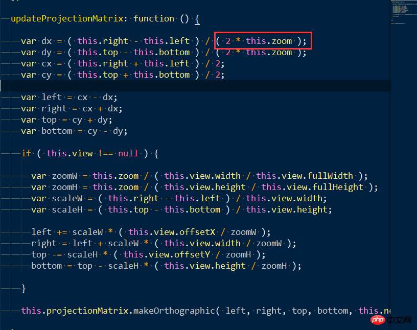
23D切换的主要内容就是当相机的视线轴与场景的平面垂直时,使用平行投影,这样用户只能看到顶面给人的感觉就是2D视图。所以要根据透视的视锥体计算出平行投影的世景体。
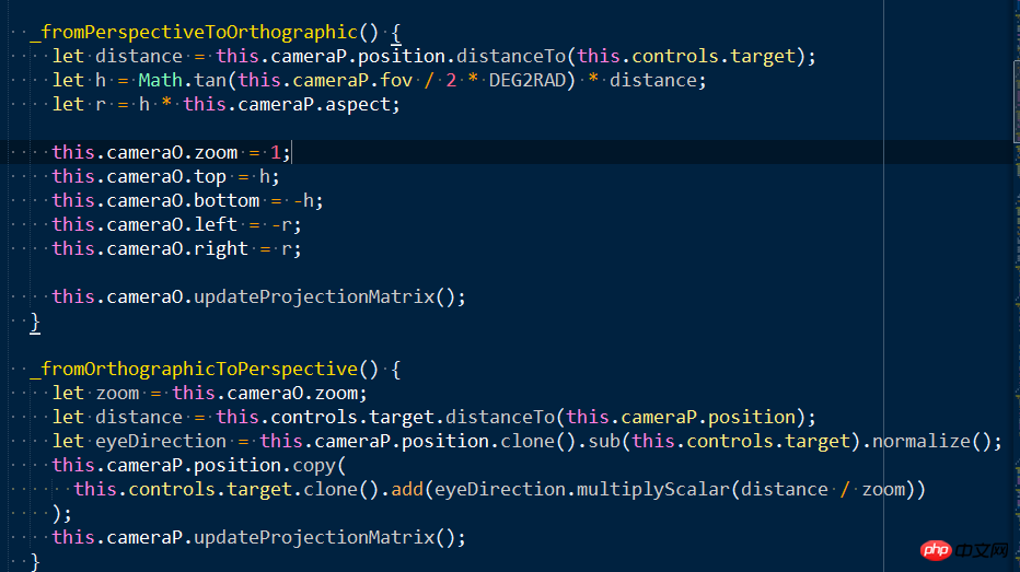
因为用户会在2D、3D场景下做很多操作,比如平移、缩放、旋转,要想无缝切换,这个关键在于将平行投影与视锥体相机的位置、lookAt方式保持一致;以及将他们放大缩小的关键点:distance的比例与zoom来保持一致。
平行投影中,zoom越大代表六面体的首尾两个面面积越小,放大越大。
8、3D中地理级别
地理级别实际是像素跟墨卡托坐标系下米的对应关系,这个有通用的标准以及计算公式:
r=6378137
resolution=2*PI*r/(2^zoom*256)
各个级别中像素与米的对应关系如下:
resolution zoom 2048 blocksize 256 blocksize scale(dpi=160)
156543.0339 0 320600133.5 40075016.69 986097851.5
78271.51696 1 160300066.7 20037508.34 493048925.8
39135.75848 2 80150033.37 10018754.17 246524462.9
19567.87924 3 40075016.69 5009377.086 123262231.4
9783.939621 4 20037508.34 2504688.543 61631115.72
4891.96981 5 10018754.17 1252344.271 30815557.86
2445.984905 6 5009377.086 626172.1357 15407778.93
1222.992453 7 2504688.543 313086.0679 7703889.465
611.4962263 8 1252344.271 156543.0339 3851944.732
305.7481131 9 626172.1357 78271.51696 1925972.366
152.8740566 10 313086.0679 39135.75848 962986.1831
76.4370283 11 156543.0339 19567.87924 481493.0916
38.2185141 12 78271.51696 9783.939621 240746.5458
19.1092571 13 39135.75848 4891.96981 120373.2729
9.5546285 14 19567.87924 2445.984905 60186.63645
4.7773143 15 9783.939621 1222.992453 30093.31822
2.3886571 16 4891.96981 611.4962263 15046.65911
1.1943286 17 2445.984905 305.7481131 7523.329556
0.5971643 18 1222.992453 152.8740566 3761.664778
0.2985821 19 611.4962263 76.43702829 1880.832389
0.1492911 20 305.7481131 38.21851414 940.4161945
0.0746455 21
0.0373227 22
3D中的计算策略是,首先需要将3D世界中的坐标与墨卡托单位的对应关系搞清楚,如果已经是以mi来做单位,那么就可以直接将相机的投影屏幕的高度与屏幕的像素数目做比值,得出的结果跟上面的ranking做比较,选择不用的级别数据以及比例尺。注意3D地图中的比例尺并不是在所有屏幕上的所有位置与现实世界都满足这个比例尺,只能说是相机中心点在屏幕位置处的像素是满足这个关系的,因为平行投影有近大远小的效果。
9、poi碰撞
由于标注是永远朝着相机的,所以标注的碰撞就是把标注点转换到屏幕坐标系用宽高来计算矩形相交问题。至于具体的碰撞算法,大家可以在网上找到,这里不展开。下面是计算poi矩形的代码
export function getPoiRect(poi, zoomLevel, wrapper) {
 let style = getStyle(poi.styleId, zoomLevel);
 if (!style) {
 console.warn("style is invalid!");
 return;
 }
 let labelStyle = getStyle(style.labelid, zoomLevel);
 if (!labelStyle) {
 console.warn("labelStyle is invalid!");
 return;
 }
 if (!poi.text) {
 return;
 }
 let charWidth = (TEXTPROP.charWidth || 11.2) * // 11.2是根据测试得到的估值
 (labelStyle.fontSize / (TEXTPROP.fontSize || 13)); // 13是得到11.2时的fontSize
 // 返回2d坐标
 let x = 0;//poi.points[0].x;
 let y = 0;//-poi.points[0].z;
 let path = [];
 let icon = iconSet[poi.styleId];
 let iconWidh = (icon && icon.width) || 32;
 let iconHeight = (icon && icon.height) || 32;
 let multi = /\//g;
 let firstLinePos = [];
 let textAlign = null;
 let baseLine = null;
 let hOffset = (iconWidh / 2) * ICONSCALE;
 let vOffset = (iconHeight / 2) * ICONSCALE;
 switch(poi.direct) {
 case 2: { // 左
 firstLinePos.push(x - hOffset - 2);
 firstLinePos.push(y);
 textAlign = 'right';
 baseLine = 'middle';
 break;
 };
 case 3: { // 下
 firstLinePos.push(x);
 firstLinePos.push(y - vOffset - 2);
 textAlign = 'center';
 baseLine = 'top';
 break;
 };
 case 4: { // 上
 firstLinePos.push(x);
 firstLinePos.push(y + vOffset + 2);
 textAlign = 'center';
 baseLine = 'bottom';
 break;
 };
 case 1:{ // 右
 firstLinePos.push(x + hOffset + 2);
 firstLinePos.push(y);
 textAlign = 'left';
 baseLine = 'middle';
 break;
 };
 default: {
 firstLinePos.push(x);
 firstLinePos.push(y);
 textAlign = 'center';
 baseLine = 'middle';
 }
 }
 path = path.concat(firstLinePos);

 let minX = null, maxX = null;
 let minY = null, maxY = null;
 let parts = poi.text.split(multi);

 let textWidth = 0;
 if (wrapper) {
 // 汉字和数字的宽度是不同的,所以必须使用measureText来精确测量
 let textWidth1 = wrapper.context.measureText(parts[0]).width;
 let textWidth2 = wrapper.context.measureText(parts[1] || '').width;
 textWidth = Math.max(textWidth1, textWidth2);
 } else {
 textWidth = Math.max(parts[0].length, parts[1] ? parts[1].length : 0) * charWidth;
 }

 if (textAlign === 'left') {
 minX = x - hOffset;
 maxX = path[0] + textWidth; // 只用第一行文本
 } else if (textAlign === 'right') {
 minX = path[0] - textWidth;
 maxX = x + hOffset;
 } else { // center
 minX = x - Math.max(textWidth / 2, hOffset);
 maxX = x + Math.max(textWidth / 2, hOffset);
 }
 if (baseLine === 'top') {
 maxY = y + vOffset;
 minY = y - vOffset - labelStyle.fontSize * parts.length;
 } else if (baseLine === 'bottom') {
 maxY = y + vOffset + labelStyle.fontSize * parts.length;
 minY = y - vOffset;
 } else { // middle
 minY = Math.min(y - vOffset, path[1] - labelStyle.fontSize / 2);
 maxY = Math.max(y + vOffset, path[1] + labelStyle.fontSize * (parts.length + 0.5 - 1));
 }

 return {
 min: {
 x: minX,
 y: minY
 },
 max: {
 x: maxX,
 y: maxY
 }
 };
}大家学会了吗?赶紧动尝试一下吧。
相关推荐:
The above is the detailed content of Three.js implements 3D map instance sharing. For more information, please follow other related articles on the PHP Chinese website!


