

cad area shortcut key


cad area shortcut key
In cad, the shortcut key for finding the area is AA. The specific operation for finding the area is The steps are as follows:
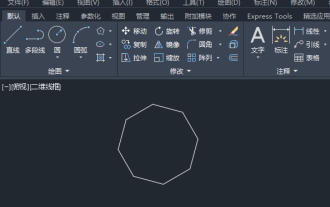
1. First, we open the CAD software. There is a polygon on the interface as shown in the figure. Now we use shortcut keys to find its area.

#2. Enter AA in the command bar, press Enter or right-click.

#3. After entering the command, follow the command prompts to select the boundary points of the polygon.

4. As shown in the figure, continue to select the area.

#5. After selecting the area, the area we selected will be displayed.

#6. After selecting the area, right-click and the area will be displayed.

The above is the detailed content of cad area shortcut key. For more information, please follow other related articles on the PHP Chinese website!

Hot AI Tools

Undresser.AI Undress
AI-powered app for creating realistic nude photos

AI Clothes Remover
Online AI tool for removing clothes from photos.

Undress AI Tool
Undress images for free

Clothoff.io
AI clothes remover

AI Hentai Generator
Generate AI Hentai for free.

Hot Article
Hot Tools

Notepad++7.3.1
Easy-to-use and free code editor

SublimeText3 Chinese version
Chinese version, very easy to use

Zend Studio 13.0.1
Powerful PHP integrated development environment

Dreamweaver CS6
Visual web development tools

SublimeText3 Mac version
God-level code editing software (SublimeText3)
Hot Topics


 cad2012 serial number and key activation code
Jun 25, 2023 pm 04:29 PM
cad2012 serial number and key activation code
Jun 25, 2023 pm 04:29 PM
cad2012 activation code: 1. 400-45454545 key: 651D1; 2. 359-23589418 key: 001D1; 3. 356-72378422 key: 001D1; 4. 400-45454545 key: 001D1; 5. 666-69696969 password Key: 001D1; 6, 667-98989898 Key: 001D1.
 Why is the CAD layer unlocked but cannot be selected?
Sep 12, 2023 pm 03:41 PM
Why is the CAD layer unlocked but cannot be selected?
Sep 12, 2023 pm 03:41 PM
The cad layer is not locked but the objects in it cannot be selected, which may be caused by the visibility, property settings, order or software problems of the layer. Detailed introduction: 1. Layer visibility, make sure the layer's visibility is set to "visible"; 2. Property settings, check the layer's property settings and make sure they match the current drawing environment; 3. Sequence , adjust the order of layers to ensure that the object to be selected is above other objects; 4. Software problems, restart the CAD software, or update to the latest version.
 Why can't CAD be copied to the clipboard?
Sep 11, 2023 pm 03:32 PM
Why can't CAD be copied to the clipboard?
Sep 11, 2023 pm 03:32 PM
Reasons why CAD cannot be copied to the clipboard may be software issues, permission restrictions, graphics complexity, clipboard issues, and improper user operation. Detailed introduction: 1. Software problems, restart the CAD software, or upgrade to the latest version; 2. Permission restrictions, you can contact the system administrator or network administrator to obtain higher permissions; 3. Graphics complexity, try to simplify the graphics , delete unnecessary objects or layers, or split the graphics into multiple smaller parts for copying; 4. Clipboard problem, try clearing the clipboard, etc.
 How to solve the problem that the top functional area of cad is missing
Dec 08, 2023 pm 05:15 PM
How to solve the problem that the top functional area of cad is missing
Dec 08, 2023 pm 05:15 PM
Solutions to the disappearance of the top functional area of CAD: 1. Shortcut key operation; 2. Menu bar operation; 3. Right-click menu operation; 4. Reset the CAD interface; 5. Adjust the display mode of the functional area; 6. Adjust the CAD interface Layout; 7. Use shortcut key combinations; 8. Customize shortcut keys; 9. Update or reinstall CAD software. Detailed introduction: 1. Shortcut key operation. In the CAD interface, if the functional area disappears, you can redisplay it by using the shortcut key; 2. Menu bar operation. In the CAD interface, open the menu bar and find the "Tools" option, etc. wait.
 What's going on with cad error interrupt fatal error
Jul 05, 2023 pm 03:02 PM
What's going on with cad error interrupt fatal error
Jul 05, 2023 pm 03:02 PM
Causes of CAD error interrupt fatal error: 1. The software version is incompatible. The solution is to upgrade to the latest version or contact the supplier for a solution; 2. Insufficient memory. The solution is to increase the computer's memory capacity or close other memory-occupying programs. application; 3. Hardware failure, the solution is to repair or replace the faulty hardware; 4. File damage, the solution includes using the repair tool provided by the CAD software, restoring the backup file or re-creating the file; 5. Illegal operation, the solution is to follow Correct operating procedures and avoid using uncertain tools and functions.
 cad break line command
Aug 08, 2023 am 11:46 AM
cad break line command
Aug 08, 2023 am 11:46 AM
The CAD break line command refers to a command used in computer-aided design software to break line segments or polylines. This command is very commonly used in CAD software because line segments often need to be modified and adjusted during the design process. Use break lines. Commands make it easy to split a line segment into multiple segments to meet design needs.
 What should I do if part of the conversion from cad to pdf is not displayed?
Jun 30, 2023 am 09:43 AM
What should I do if part of the conversion from cad to pdf is not displayed?
Jun 30, 2023 am 09:43 AM
Solution to the problem that part of the CAD to PDF conversion cannot be displayed: 1. Re-adjust the layer settings in CAD to ensure that the content in all layers is displayed correctly; 2. Use some professional software to convert the CAD file to ensure the clarity of the output file. and accuracy, and batch output saves time and improves efficiency; 3. Optimize CAD files and delete unnecessary layers and elements to reduce file size and complexity; 4. Use a PDF viewer that supports the current PDF version .
 How to draw three-dimensional graphics in CAD
Feb 27, 2024 pm 07:00 PM
How to draw three-dimensional graphics in CAD
Feb 27, 2024 pm 07:00 PM
In CAD software, the three-dimensional drawing function allows designers to express design concepts more intuitively and create three-dimensional graphics. However, many users may not yet understand how to use CAD to draw three-dimensional graphics, so this article will introduce you in detail how to use CAD software to draw three-dimensional graphics to help you master this key skill. If you want to know more, please continue reading this article. I believe this tutorial guide will be helpful to you. Steps for drawing three-dimensional graphics in CAD: 1. Open the CAD2023 software and create a blank document. Create an 8-sided shape. As shown below: 2. Click the area tool in the drawing. Or enter a space after entering the REGION command. As shown below: 3. Select the object in REGION.