 Operation and Maintenance
 Linux Operation and Maintenance
 About Cache Memory of Linux (detailed picture and text explanation)
About Cache Memory of Linux (detailed picture and text explanation)

About Linux’s cache memory Cache Memory (detailed graphic and text explanation)
The topic of today’s exploration is cache. We revolve around several questions. Why do you need cache? How to determine whether a data hit in the cache? What are the types of cache and what are the differences?
Why cache memory is needed
Before thinking about what cache is, let’s first think about the first question: How does our program run? We should know that the program runs in RAM, and RAM is what we often call DDR (such as DDR3, DDR4, etc.). We call it main memory. When we need to run a process, we first load the executable program from the Flash device (for example, eMMC, UFS, etc.) into main memory, and then start execution. There are a bunch of general-purpose registers (registers) inside the CPU. If the CPU needs to add 1 to a variable (assuming the address is A), it is generally divided into the following three steps:
CPU reads the data at address A from the main memory to Internal general-purpose register x0 (one of the general-purpose registers of the ARM64 architecture).
Add 1 to general register x0.
CPU writes the value of general register x0 to main memory.
We can express this process as follows:
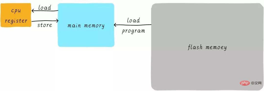
In fact, in reality, the speed of the CPU general register and the main memory There is a huge difference between them. The speed relationship between the two is roughly as follows:

The speed of CPU register is generally less than 1ns, and the speed of main memory is generally about 65ns. The speed difference is nearly a hundred times. Therefore, among the three steps in the above example, steps 1 and 3 are actually very slow. When the CPU tries to load/store operations from the main memory, the CPU has to wait for this long 65ns due to the speed limit of the main memory. If we can increase the speed of main memory, then the system will get a huge performance improvement.
Today's DDR storage devices can easily have several GB, with a large capacity. If we use faster materials to make faster main memory, and have almost the same capacity. Its cost will rise significantly. We are trying to increase the speed and capacity of main memory while expecting the cost to be very low, which is a bit embarrassing. Therefore, we have a compromise method, which is to make a storage device that is extremely fast but has extremely small capacity. Then the cost will not be too high. We call this storage device cache memory.
In terms of hardware, we place the cache between the CPU and the main memory as a cache of main memory data. When the CPU attempts to load/store data from main memory, the CPU will first check from the cache to see whether the data at the corresponding address is cached in the cache. If the data is cached in the cache, the data is obtained directly from the cache and returned to the CPU. When there is a cache, the process of the above example of how the program runs will become as follows:

The direct data transmission method between the CPU and the main memory changes to the method of direct data transmission between the CPU and the main memory. Direct data transfer between caches. The cache is responsible for data transfer between main memory and main memory.
Multi-level cache memory
The speed of the cache also affects the performance of the system to a certain extent.
Generally, the cache speed can reach 1ns, which is almost comparable to the CPU register speed. But, does this satisfy people’s pursuit of performance? not at all. When the data we want is not cached in the cache, we still need to wait for a long time to load the data from main memory. In order to further improve performance, multi-level cache is introduced.
The cache mentioned earlier is called L1 cache (first level cache). We connect the L2 cache behind the L1 cache, and connect the L3 cache between the L2 cache and the main memory. The higher the level, the slower the speed and the greater the capacity. But compared to main memory, the speed is still very fast. The relationship between different levels of cache speed is as follows:

After the buffering of level 3 cache, the speed difference between each level of cache and main memory also decreases step by step. In a real system, how are the hardware related between caches at all levels? Let’s take a look at the hardware abstract block diagram between caches at all levels on the Cortex-A53 architecture as follows:
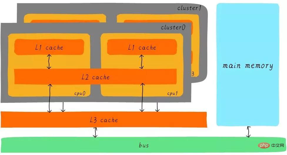
On the Cortex-A53 architecture, the L1 cache is divided into separate instruction cache (ICache) and data cache (DCache). The L1 cache is private to the CPU, and each CPU has an L1 cache. All CPUs in a cluster share an L2 cache. The L2 cache does not distinguish between instructions and data, and can cache both. The L3 cache is shared among all clusters. L3 cache is connected to main memory through a bus.
Cooperation between multi-level caches
First introduce two noun concepts, hits and misses. The data that the CPU wants to access is cached in the cache, which is called a "hit", and vice versa is called a "miss". How do multi-level caches work together? We assume that the system under consideration has only two levels of cache.
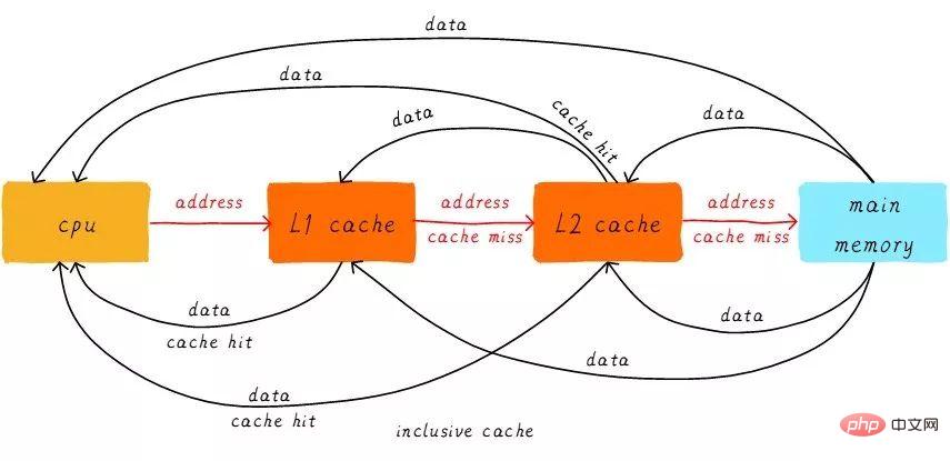
When the CPU tries to load data from an address, it first checks whether there is a hit from the L1 cache. If it hits, the data is returned to the CPU. If the L1 cache is missing, continue searching from the L2 cache. When the L2 cache hits, the data will be returned to the L1 cache and CPU. If the L2 cache is also missing, unfortunately, we need to load the data from the main memory and return the data to the L2 cache, L1 cache and CPU. This multi-level cache working method is called inclusive cache.
Data at a certain address may exist in multi-level caches. Corresponding to the inclusive cache is the exclusive cache, which ensures that the data cache at a certain address will only exist in one level of the multi-level cache. In other words, data at any address cannot be cached in L1 and L2 cache at the same time.
Direct mapped cache
We continue to introduce some cache-related terms. The size of the cache is called cache size, which represents the size of the maximum data that the cache can cache. We divide the cache into many equal blocks, and the size of each block is called a cache line, and its size is the cache line size.
For example, a cache of 64 Bytes size. If we divide 64 Bytes into 64 blocks equally, then the cache line is 1 byte, and there are 64 cache lines in total. If we divide the 64 Bytes into 8 blocks equally, then the cache line is 8 bytes, and there are 8 cache lines in total. In current hardware design, the general cache line size is 4-128 Byts. Why is there not 1 byte? We will discuss the reasons later.
One thing to note here is that cache line is the smallest unit of data transfer between cache and main memory. What does that mean? When the CPU attempts to load a byte of data, if the cache is missing, the cache controller will load cache line-sized data from main memory into the cache at once. For example, the cache line size is 8 bytes. Even if the CPU reads one byte, after the cache is missing, the cache will load 8 bytes from the main memory to fill the entire cache line. And why? You’ll understand after I finish talking about it.
We assume that the following explanations are for a cache of 64 Bytes size, and the cache line size is 8 bytes. We can think of this cache as an array. The array has a total of 8 elements, and the size of each element is 8 bytes. Just like the picture below.

Now we consider a problem. The CPU reads a byte from address 0x0654. How does the cache controller determine whether the data is hit in the cache? The cache size is dwarfed by the main memory. So the cache must only be able to cache a very small part of the data in the main memory. How do we find data in a limited-size cache based on address? The current approach taken by hardware is to hash the address (which can be understood as an address modulo operation). Let's see how it is done next?

We have a total of 8 cache lines, and the cache line size is 8 Bytes. So we can use the lower 3 bits of the address (as shown in the blue part of the address above) to address a certain byte in 8 bytes. We call this bit combination offset. In the same way, 8 lines of cache lines are used to cover all lines.
We need 3 bits (as shown in the yellow part of the address above) to find a certain line. This part of the address is called index. Now we know that if the bit3-bit5 of two different addresses are exactly the same, then the two addresses will find the same cache line after hardware hashing. Therefore, when we find the cache line, it only means that the data corresponding to the address we accessed may exist in this cache line, but it may also be data corresponding to other addresses. Therefore, we introduce the tag array area, and the tag array and data array correspond one to one.
Each cache line corresponds to a unique tag. What is stored in the tag is the remaining bit width of the entire address excluding the bits used by index and offset (as shown in the green part of the address above). The combination of tag, index and offset can uniquely determine an address. Therefore, when we find the cache line based on the index bit in the address, we take out the tag corresponding to the current cache line, and then compare it with the tag in the address. If they are equal, it means a cache hit. If they are not equal, it means that the current cache line stores data at other addresses, which is a cache miss.
In the above figure, we see that the value of tag is 0x19, which is equal to the tag part of the address, so it will hit during this access. Due to the introduction of tag, one of our previous questions was answered "Why is the hardware cache line not made into one byte?". This will lead to an increase in hardware costs, because originally 8 bytes corresponded to a tag, but now 8 tags are needed, occupying a lot of memory.
We can see from the picture that there is a valid bit next to the tag. This bit is used to indicate whether the data in the cache line is valid (for example: 1 means valid; 0 means invalid). When the system first starts, the data in the cache should be invalid because no data has been cached yet. The cache controller can confirm whether the current cache line data is valid based on the valid bit. Therefore, before the above comparison tag confirms whether the cache line is hit, it will also check whether the valid bit is valid. Comparing tags only makes sense if they are valid. If it is invalid, it is directly determined that the cache is missing.
In the above example, cache size is 64 Bytes and cache line size is 8 bytes. Offset, index and tag use 3 bits, 3 bits and 42 bits respectively (assuming the address width is 48 bits). Let's look at another example now: 512 Bytes cache size, 64 Bytes cache line size. According to the previous address division method, offset, index and tag use 6 bits, 3 bits and 39 bits respectively. As shown below.

The advantages and disadvantages of direct mapped cache
Direct mapped cache will be simpler in hardware design, so the cost will be lower Low. According to the working method of direct mapping cache, we can draw the cache distribution diagram corresponding to the main memory address 0x00-0x88.
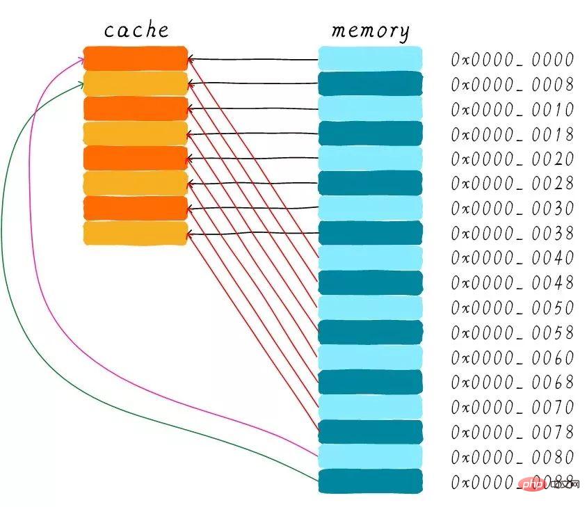
We can see that the data corresponding to the address 0x00-0x3f can cover the entire cache. The data at addresses 0x40-0x7f also covers the entire cache. Let's think about a question now. If a program tries to access addresses 0x00, 0x40, and 0x80 in sequence, what will happen to the data in the cache?
First of all, we should understand that the index part of the 0x00, 0x40, and 0x80 addresses is the same. Therefore, the cache lines corresponding to these three addresses are the same. So, when we access address 0x00, the cache will be missing, and then the data will be loaded from main memory into cache line 0. When we access the 0x40 address, we still index the 0th cache line in the cache. Since the cache line stores the data corresponding to the address 0x00 at this time, the cache will still be missing at this time. Then load the 0x40 address data from the main memory into the first cache line. In the same way, if you continue to access the 0x80 address, the cache will still be missing.
This is equivalent to reading data from the main memory every time, so the existence of cache does not improve performance. When accessing address 0x40, the data cached at address 0x00 will be replaced. This phenomenon is called cache thrashing. To solve this problem, we introduce multi-way group connected cache. Let's first study how the simplest two-way set-connected cache works.
Two-way set associative cache (Two-way set associative cache)
We still assume that the cache size is 64 Bytes and the cache line size is 8 Bytes. What is the concept of road? We divide the cache into multiple equal parts, and each part is a way. Therefore, the two-way set-connected cache divides the cache into two equal parts, each part is 32 Bytes. As shown below.
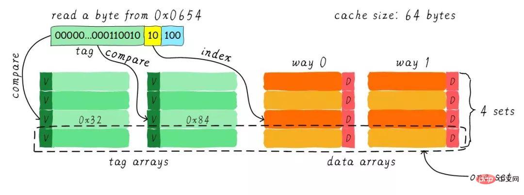
#The cache is divided into 2 paths, each path contains 4 cache lines. We group all cache lines with the same index together and call them groups. For example, in the figure above, a group has two cache lines, for a total of 4 groups. We still assume that one byte of data is read from address 0x0654. Since the cache line size is 8 Bytes, the offset requires 3 bits, which is the same as the previous direct mapping cache. The difference is the index. In a two-way set-connected cache, the index only requires 2 bits because there are only 4 cache lines in one way.
The above example finds the 2nd cache line based on the index (calculated from 0). The 2nd line corresponds to 2 cache lines, corresponding to way 0 and way 1 respectively. Therefore index can also be called set index (group index). First find the set according to the index, and then take out the tags corresponding to all cache lines in the group and compare them with the tag part in the address. If one of them is equal, it means a hit.
Therefore, the biggest difference between the two-way set-connected cache and the direct-mapped cache is that the data corresponding to the first address can correspond to 2 cache lines, while in the direct-mapped cache, one address only corresponds to one cache line. So what exactly are the benefits of this?
Advantages and disadvantages of two-way set-connected cache
The hardware cost of two-way set-connected cache is higher than that of direct-mapped cache. Because each time it compares tags, it needs to compare tags corresponding to multiple cache lines (some hardware may also perform parallel comparisons to increase the comparison speed, which increases the complexity of hardware design).
Why do we still need two-way group connected cache? Because it can help reduce the possibility of cache thrashing. So how is it reduced? According to the working method of the two-way set-connected cache, we can draw the cache distribution diagram corresponding to the main memory address 0x00-0x4f.
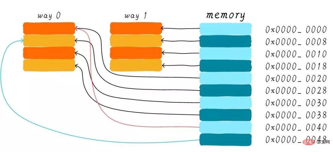
We still consider the question in the direct-mapped cache section "If a program tries to access addresses 0x00, 0x40, and 0x80 in sequence, what will happen to the data in the cache?". Now the data at address 0x00 can be loaded into way 1, and 0x40 can be loaded into way 0. Does this avoid the embarrassing situation of direct mapping cache to a certain extent? In the case of two-way set-connected cache, the data at addresses 0x00 and 0x40 are cached in the cache. Just imagine, if we use a 4-way group connection cache, if we continue to access 0x80 later, it may also be cached.
Therefore, when the cache size is certain, the performance improvement of group-connected cache is the same as that of direct-mapped cache in the worst case. In most cases, the effect of group-connected cache is better than that of direct-mapped cache. At the same time, it reduces the frequency of cache thrashing. To some extent, direct-mapped cache is a special case of set-linked cache, with only one cache line per group. Therefore, a direct-mapped cache can also be called a one-way set-connected cache.
Full associative cache (Full associative cache)
Since group-associated cache is so good, if all cache lines are in a group. Wouldn't the performance be better? Yes, this kind of cache is a fully connected cache. We still take the 64 Byts size cache as an example.
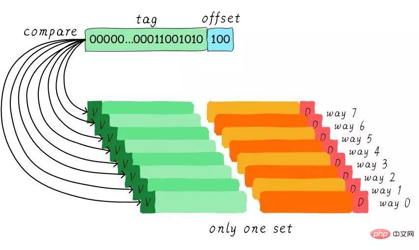
Since all cache lines are in a group, the set index part is not required in the address. Because there is only one group for you to choose, which indirectly means you have no choice. We compare the tag part in the address with the tags corresponding to all cache lines (the hardware may perform parallel or serial comparisons). Which tag is equal means that a certain cache line is hit. Therefore, in a fully connected cache, data at any address can be cached in any cache line. Therefore, this can minimize the frequency of cache thrashing. But the hardware cost is also higher.
A four-way group connected cache instance problem
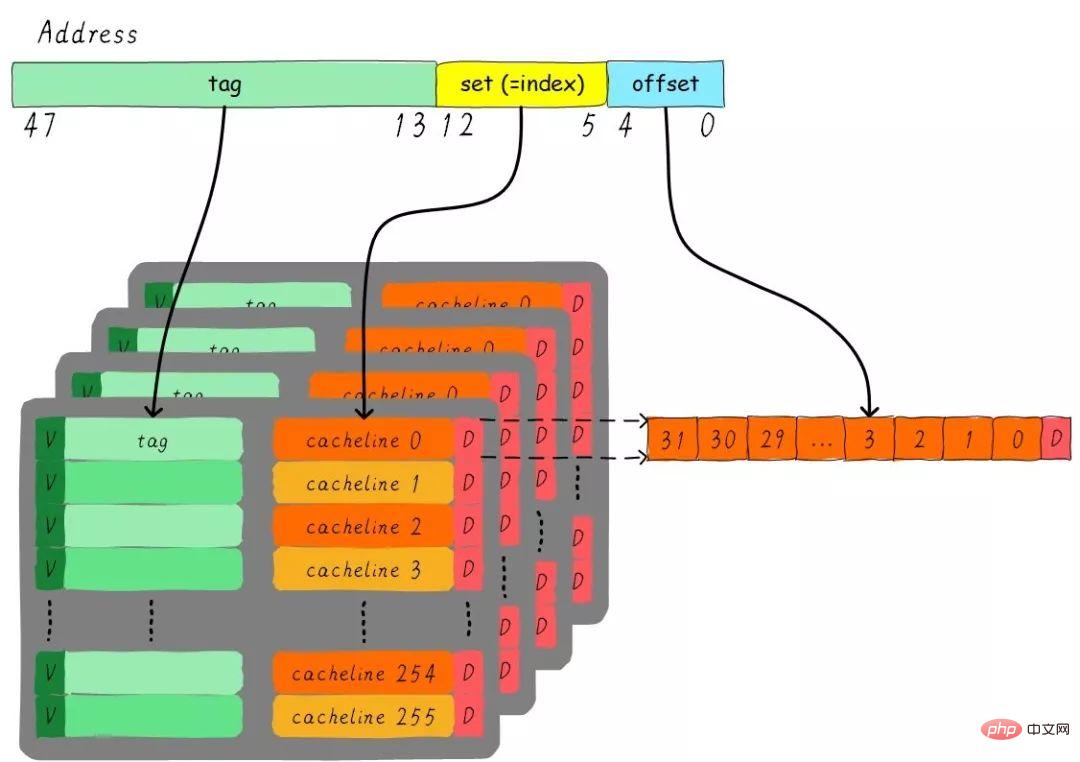
Consider such a problem, a 32 KB size 4-way group connected cache, the cache line size is 32 Bytes. Please think about the questions:
1). How many groups are there? 2). Assuming that the address width is 48 bits, how many bits do index, offset and tag occupy respectively?
There are 4 channels in total, so the size of each channel is 8 KB. The cache line size is 32 Bytes, so there are 256 groups (8 KB / 32 Bytes) in total. Since the cache line size is 32 Bytes, the offset requires 5 bits. There are 256 groups in total, so the index requires 8 bits, and the rest is the tag part, which takes up 35 bits. This cache can be represented by the following figure.
Cache allocation policy
The cache allocation policy refers to the circumstances under which we should allocate cache for data line. The cache allocation strategy is divided into two situations: read and write.
Read allocation:
When the CPU reads data, a cache miss occurs. In this case, a cache line cache will be allocated to read from the main memory. The data. By default, caches support read allocation.
Write allocation:
When the CPU writes data and the cache is missing, the write allocation strategy will be considered. When we do not support write allocation, the write instruction will only update the main memory data and then end. When write allocation is supported, we first load data from main memory into the cache line (equivalent to doing a read allocation first), and then update the data in the cache line.
Cache update policy (Cache update policy)
The cache update policy refers to how write operations should update data when a cache hit occurs. Cache update strategies are divided into two types: write-through and write-back.
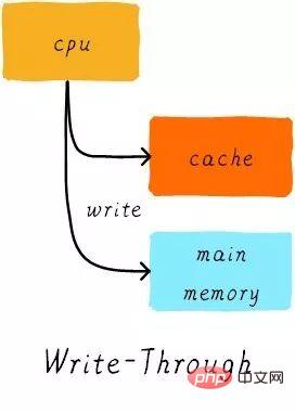
Write through (write through):
When the CPU executes the store instruction and the cache hits, we update the data in the cache and update the data in the main memory. The data in cache and main memory are always consistent.
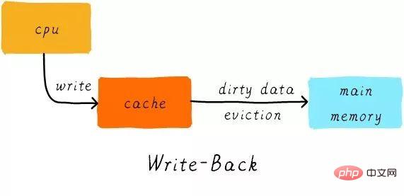
Write back:
When the CPU executes the store instruction and the cache hits, we only update the cache The data. And there will be a bit in each cache line to record whether the data has been modified, called a dirty bit (look at the previous picture, there is a D next to the cache line, which is the dirty bit). We will set the dirty bit. Data in main memory is only updated when the cache line is replaced or a clean operation is performed. Therefore, the data in main memory may be unmodified data, while the modified data lies in the cache line.
At the same time, why is the cache line size the smallest unit of data transfer between the cache controller and main memory? This is also because each cache line has only one dirty bit. This dirty bit represents the modified status of the entire cache line.
Example
Suppose we have a 64 Bytes size direct mapped cache, the cache line size is 8 Bytes, using write allocation and Write back mechanism. When the CPU reads a byte from address 0x2a, how will the data in the cache change? Assume that the current cache status is as shown in the figure below.
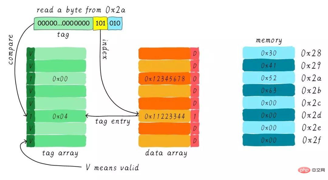
Find the corresponding cache line according to the index. The valid bit of the corresponding tag part is legal, but the value of the tag is not equal, so a deletion occurs. At this time we need to load 8 bytes of data from address 0x28 into the cache line. However, we found that the dirty bit of the current cache line is set. Therefore, the data in the cache line cannot be simply discarded. Due to the write-back mechanism, we need to write the data 0x11223344 in the cache to the address 0x0128 (this address is calculated based on the value in the tag and the cache line where it is located) ). This process is shown in the figure below.
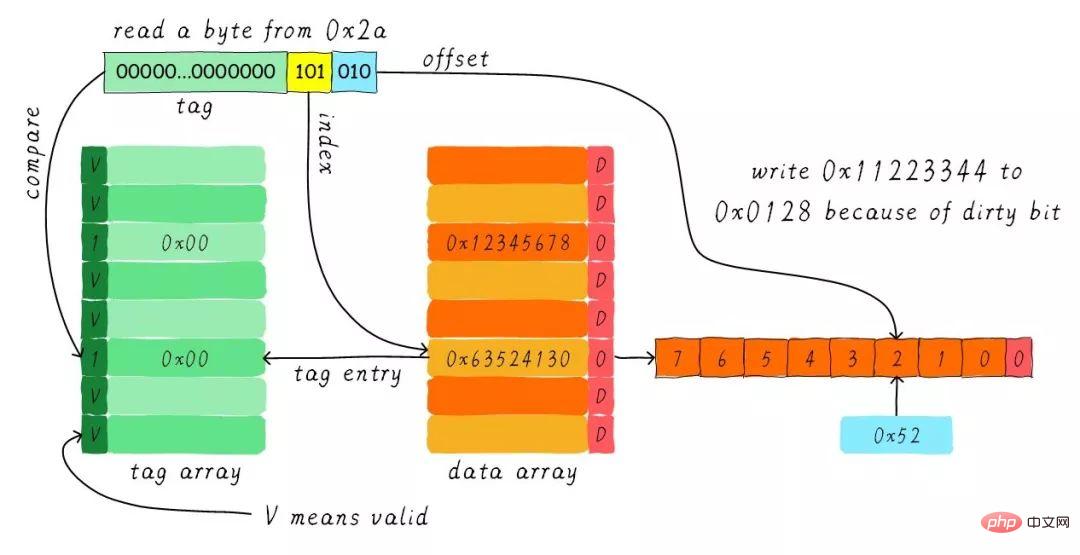
When the write-back operation is completed, we load the 8 bytes starting at address 0x28 in the main memory into the cache line and clear the dirty bit. Then find 0x52 according to the offset and return it to the CPU.
Thank you for your patience in reading, I hope you can benefit from it.
This article is reproduced from Wowotech: http://www.wowotech.net/memory_management/458.html
Recommended tutorial: "Linux Operation and Maintenance"
The above is the detailed content of About Cache Memory of Linux (detailed picture and text explanation). For more information, please follow other related articles on the PHP Chinese website!

Hot AI Tools

Undresser.AI Undress
AI-powered app for creating realistic nude photos

AI Clothes Remover
Online AI tool for removing clothes from photos.

Undress AI Tool
Undress images for free

Clothoff.io
AI clothes remover

Video Face Swap
Swap faces in any video effortlessly with our completely free AI face swap tool!

Hot Article

Hot Tools

Notepad++7.3.1
Easy-to-use and free code editor

SublimeText3 Chinese version
Chinese version, very easy to use

Zend Studio 13.0.1
Powerful PHP integrated development environment

Dreamweaver CS6
Visual web development tools

SublimeText3 Mac version
God-level code editing software (SublimeText3)

Hot Topics
 1387
1387
 52
52
 How to use docker desktop
Apr 15, 2025 am 11:45 AM
How to use Docker Desktop? Docker Desktop is a tool for running Docker containers on local machines. The steps to use include: 1. Install Docker Desktop; 2. Start Docker Desktop; 3. Create Docker image (using Dockerfile); 4. Build Docker image (using docker build); 5. Run Docker container (using docker run).
 How to view the docker process
Apr 15, 2025 am 11:48 AM
Docker process viewing method: 1. Docker CLI command: docker ps; 2. Systemd CLI command: systemctl status docker; 3. Docker Compose CLI command: docker-compose ps; 4. Process Explorer (Windows); 5. /proc directory (Linux).
 What to do if the docker image fails
Apr 15, 2025 am 11:21 AM
Troubleshooting steps for failed Docker image build: Check Dockerfile syntax and dependency version. Check if the build context contains the required source code and dependencies. View the build log for error details. Use the --target option to build a hierarchical phase to identify failure points. Make sure to use the latest version of Docker engine. Build the image with --t [image-name]:debug mode to debug the problem. Check disk space and make sure it is sufficient. Disable SELinux to prevent interference with the build process. Ask community platforms for help, provide Dockerfiles and build log descriptions for more specific suggestions.
 vscode cannot install extension
Apr 15, 2025 pm 07:18 PM
The reasons for the installation of VS Code extensions may be: network instability, insufficient permissions, system compatibility issues, VS Code version is too old, antivirus software or firewall interference. By checking network connections, permissions, log files, updating VS Code, disabling security software, and restarting VS Code or computers, you can gradually troubleshoot and resolve issues.
 What computer configuration is required for vscode
Apr 15, 2025 pm 09:48 PM
VS Code system requirements: Operating system: Windows 10 and above, macOS 10.12 and above, Linux distribution processor: minimum 1.6 GHz, recommended 2.0 GHz and above memory: minimum 512 MB, recommended 4 GB and above storage space: minimum 250 MB, recommended 1 GB and above other requirements: stable network connection, Xorg/Wayland (Linux)
 Can vscode be used for mac
Apr 15, 2025 pm 07:36 PM
VS Code is available on Mac. It has powerful extensions, Git integration, terminal and debugger, and also offers a wealth of setup options. However, for particularly large projects or highly professional development, VS Code may have performance or functional limitations.
 What is vscode What is vscode for?
Apr 15, 2025 pm 06:45 PM
VS Code is the full name Visual Studio Code, which is a free and open source cross-platform code editor and development environment developed by Microsoft. It supports a wide range of programming languages and provides syntax highlighting, code automatic completion, code snippets and smart prompts to improve development efficiency. Through a rich extension ecosystem, users can add extensions to specific needs and languages, such as debuggers, code formatting tools, and Git integrations. VS Code also includes an intuitive debugger that helps quickly find and resolve bugs in your code.
 How to back up vscode settings and extensions
Apr 15, 2025 pm 05:18 PM
How to back up VS Code configurations and extensions? Manually backup the settings file: Copy the key JSON files (settings.json, keybindings.json, extensions.json) to a safe location. Take advantage of VS Code synchronization: enable synchronization with your GitHub account to automatically back up all relevant settings and extensions. Use third-party tools: Back up configurations with reliable tools and provide richer features such as version control and incremental backups.


