
 Common Problem
In a microcomputer, what are the arithmetic unit and the controller collectively called?
Common Problem
In a microcomputer, what are the arithmetic unit and the controller collectively called?
In a microcomputer, what are the arithmetic unit and the controller collectively called?

In a microcomputer, the arithmetic unit and controller are collectively called "microprocessor". A microprocessor is a central processing unit composed of one or a few large-scale integrated circuits; generally speaking, a microprocessor chip is integrated with components such as controllers, arithmetic units, registers, and internal buses connecting them.

#In a microcomputer, the arithmetic unit and the controller are collectively called a "microprocessor".
Microprocessor is a central processing unit composed of one or a few large-scale integrated circuits. These circuits perform the functions of control components and arithmetic logic components.
Generally speaking, microprocessor chips are integrated with components such as controllers, arithmetic units, registers, and internal buses connecting them.
The microprocessor can complete operations such as fetching instructions, executing instructions, and exchanging information with external memory and logic components. It is the computing control part of the microcomputer. It can be combined with memory and peripheral circuit chips to form a microcomputer.
Composition
The microprocessor consists of an arithmetic logic unit (ALU, Arithmetic Logical Unit); an accumulator and a general-purpose register group; a program counter ( Also called instruction indicator); timing and control logic components; data and address latches/buffers; internal bus composition. The operator and controller are its main components.
Arithmetic logic unit
The arithmetic logic unit ALU mainly completes arithmetic operations (, -, ×, ÷, comparison) and various logical operations (AND, OR, NOT , XOR, shift) and other operations. ALU is a combinational circuit and does not have the function of registering operands. Therefore, it must have two registers to store operands: temporary register TMP and accumulator AC. The accumulator not only provides operands to ALU but also receives the operation results of ALU.
The register array is actually equivalent to the RAM inside the microprocessor. It includes two parts: a general register group and a special register group. The general registers (A, B, C, D) are used to store data participating in operations. Intermediate results or addresses. They can generally be used as two 8-bit registers. With these registers inside the processor, frequent access to the memory can be avoided, the instruction length and instruction execution time can be shortened, the machine's running speed can be improved, and programming can be facilitated. Special registers include program counter PC, stack pointer SP and flag register FR. Their functions are fixed and are used to store addresses or address base values. Among them:
A) The program counter PC is used to store the address of the next instruction to be executed, so it controls the execution sequence of the program. Under the condition of sequential execution of instructions, every time a byte of the instruction is fetched, the content of PC is automatically increased by 1. When a program transfer occurs, the new instruction address (target address) must be loaded into the PC, which is usually implemented by a transfer instruction.
B) The stack pointer SP is used to store the top address of the stack. The stack is a specific area in memory. It works according to the "last in first out" method. When new data is pushed into the stack, the original information in the stack remains unchanged, and only the top position of the stack changes. When data is popped from the stack, the data at the top of the stack is popped. Automatically adjust the top position of the stack. In other words, when data is pushed or popped from the stack, it is always performed on the top of the stack. Once the stack is initialized (that is, the position of the bottom of the stack in memory is determined), the contents of the SP (that is, the position of the top of the stack) are automatically managed by the CPU.
C) The flag register is also called the program status word (PSW) register, which is used to store the result characteristics after the execution of arithmetic and logical operation instructions. For example, when the result is 0, a carry or overflow flag is generated, etc.
Timing and control logic is the core control component of the microprocessor. It is responsible for controlling the entire computer, including fetching instructions from the memory, analyzing instructions (i.e. instruction decoding) to determine the instruction operation and operand address, and fetching instructions. Operands, perform operations specified by instructions, send operation results to memory or I/O ports, etc. It also sends corresponding control signals to other components of the microcomputer to coordinate the internal and external components of the CPU.
The internal bus is used to connect the functional components of the microprocessor and transmit data and control signals within the microprocessor.
It must be pointed out that the microprocessor itself cannot constitute an independent working system, nor can it independently execute programs. It must be equipped with memory and input and output devices to form a complete microcomputer before it can work independently.
Memory
The memory of a microcomputer is used to store programs and data that are currently in use or frequently used. Memories are divided into random access memory (RAM) and read-only memory (ROM) based on read and write methods. RAM is also called read/write memory. During work, the CPU can read or write its contents at any time as needed. RAM is volatile memory, that is, its contents will be lost when the power is turned off, so it can only store temporary programs and data. The contents of ROM can only be read but not written. The information stored in the ROM remains unchanged after the power is turned off. It is a non-volatile memory. Therefore, ROM is often used to store permanent programs and data. Such as initial boot program, monitoring program, basic input and output management program BIOS in the operating system, etc.
I/O interface
The input/output interface circuit is an important component of the microcomputer. It is a logic control circuit that connects the microcomputer to external input and output devices and various control objects and exchanges information with the outside world. Since peripherals have different structures, working speeds, signal forms, and data formats, they cannot be directly connected to the system bus. Input/output interface circuits must be used for intermediate conversion to achieve information exchange with the CPU. . The I/O interface is also called an I/O adapter, and different peripherals must be equipped with different I/O adapters. I/O interface circuit is an indispensable and important part of microcomputer application system. The development and design of any microcomputer application system is actually mainly the development and design of I/O interfaces. Therefore, I/O interface technology is one of the important contents discussed in this course, and we will introduce it in detail in Chapter 8.
Bus
The bus is a common channel for transmitting information between components in the computer system and is an important component of the microcomputer. It consists of several communication lines and various three-state gate devices for driving and isolation. The structure of microcomputers always adopts a bus structure, that is, the functional components that constitute the microcomputer (microprocessor, memory, I/O interface circuit, etc.) are connected through a bus. This is a unique structure of microcomputer systems. at. After adopting the bus structure, the mutual relationship between the functional components in the system is transformed into a single relationship between each component facing the bus. As long as a component (functional board/card) conforms to the bus standard, it can be connected to the system using this bus standard. , thus making it easy to expand or update system functions, simple structure, and greatly improved reliability. In microcomputers, buses can be divided into the following four levels according to their location and application, as shown in Figure 1.4.
(1) On-chip bus: It is located inside the microprocessor chip, so it is called the chip internal bus. It is used for interconnection and information transmission between components such as the internal ALU and various registers of the microprocessor (the internal bus in Figure 1.3 is the on-chip bus). Due to limitations of the chip area and the number of external pins, most on-chip buses adopt a single bus structure, which is conducive to improving chip integration and yield. If it is required to speed up internal data transmission, a dual bus or three bus structure can also be used. .
(2) Chip bus: Chip bus is also called component level (chip level) bus or local bus. Microcomputer motherboards, single triggers, and other plug-in boards and cards (such as various I/O interface boards/cards) are themselves a complete subsystem. The board/card contains CPU, RAM, ROM, and I/O interfaces. Various chips such as these are also connected through buses, because this helps simplify the structure, reduce connections, improve reliability, and facilitate information transmission and control. The bus that connects chips on various boards and cards is usually called a chip bus or a component-level bus.
Compared to a complete microcomputer, various boards/cards are just a subsystem and a part. Therefore, the chip bus is also called a local bus, and the chip bus is used to connect the functional components of the microcomputer. The bus of the plug-in card is called the system bus. The local bus is an important concept that we will discuss in Chapter 7.
(3) Internal bus: The internal bus is also called the system bus or board-level bus. Because this bus is used to connect the functional components of the microcomputer to form a complete microcomputer system, as shown in Figure 1.2, it is called a system bus. The system bus is the most important bus in the microcomputer system. What people usually call the microcomputer bus refers to the system bus, such as PC bus, AT bus (ISA bus), PCI bus, etc. The system bus is one of the key points we will discuss.
The information transmitted on the system bus includes data information, address information, and control information. Therefore, the system bus contains buses with three different functions, namely data bus DB (Data Bus) and address bus AB (Address Bus). and control bus CB (Control Bus), as shown in Figure 1.2.
The data bus DB is used to transmit data information. The data bus is a bidirectional three-state bus, that is, it can transmit data from the CPU to other components such as memory or I/O interfaces, and can also transmit data from other components to the CPU. The number of bits in the data bus is an important indicator of a microcomputer and is usually consistent with the word length of the microprocessor. For example, the word length of the Intel 8086 microprocessor is 16 bits, and its data bus width is also 16 bits. It should be pointed out that the meaning of data is broad. It can be real data, instruction code or status information, and sometimes even control information. Therefore, in actual work, what is transmitted on the data bus is not necessarily just It is data in the true sense.
The address bus AB is specially used to transmit addresses. Since the address can only be transmitted from the CPU to the external memory or I/O port, the address bus is always one-way three-state, which is different from the data bus. The number of bits in the address bus determines the size of the memory space that the CPU can directly address. For example, if the address bus of an 8-bit microcomputer is 16 bits, its maximum addressable space is 2^16=64KB, and the address bus of a 16-bit microcomputer is 2^16=64KB. 20 bits, its addressable space is 2^20=1MB. Generally speaking, if the address bus is n bits, the addressable space is 2^n bytes.
The control bus CB is used to transmit control signals and timing signals. Among the control signals, some are sent by the microprocessor to the memory and I/O interface circuits, such as read/write signals, chip select signals, interrupt response signals, etc.; some are fed back to the CPU by other components, such as: interrupt application signals, reset signal, bus request signal, limited ready signal, etc. Therefore, the transmission direction of the control bus is determined by the specific control signal, which is generally bidirectional. The number of bits in the control bus is determined according to the actual control needs of the system. In fact, the specific situation of the control bus mainly depends on the CPU.
(4) External bus: also called communication bus. It is used for connection and communication between two systems, such as communication between two microcomputer systems, or between a microcomputer system and other electronic instruments or electronic equipment. Commonly used communication buses include IEEE-488 bus, VXI bus and RS-232 serial bus. The external bus is not inherent in the microcomputer system itself, but is only found in microcomputer application systems.
The above is the detailed content of In a microcomputer, what are the arithmetic unit and the controller collectively called?. For more information, please follow other related articles on the PHP Chinese website!

Hot AI Tools

Undresser.AI Undress
AI-powered app for creating realistic nude photos

AI Clothes Remover
Online AI tool for removing clothes from photos.

Undress AI Tool
Undress images for free

Clothoff.io
AI clothes remover

AI Hentai Generator
Generate AI Hentai for free.

Hot Article
Hot Tools

Notepad++7.3.1
Easy-to-use and free code editor

SublimeText3 Chinese version
Chinese version, very easy to use

Zend Studio 13.0.1
Powerful PHP integrated development environment

Dreamweaver CS6
Visual web development tools

SublimeText3 Mac version
God-level code editing software (SublimeText3)
Hot Topics
 1378
1378
 52
52

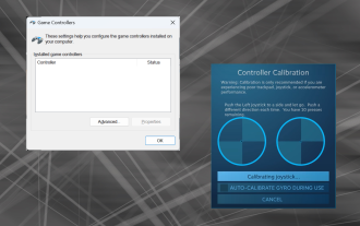 How to properly calibrate your Xbox One controller on Windows 11
Sep 21, 2023 pm 09:09 PM
How to properly calibrate your Xbox One controller on Windows 11
Sep 21, 2023 pm 09:09 PM
Since Windows has become the gaming platform of choice, it's even more important to identify its gaming-oriented features. One of them is the ability to calibrate an Xbox One controller on Windows 11. With built-in manual calibration, you can get rid of drift, random movement, or performance issues and effectively align the X, Y, and Z axes. If the available options don't work, you can always use a third-party Xbox One controller calibration tool. Let’s find out! How do I calibrate my Xbox controller on Windows 11? Before proceeding, make sure you connect your controller to your computer and update your Xbox One controller's drivers. While you're at it, also install any available firmware updates. 1. Use Wind
 How to use CodeIgniter4 framework in php?
May 31, 2023 pm 02:51 PM
How to use CodeIgniter4 framework in php?
May 31, 2023 pm 02:51 PM
PHP is a very popular programming language, and CodeIgniter4 is a commonly used PHP framework. When developing web applications, using frameworks is very helpful. It can speed up the development process, improve code quality, and reduce maintenance costs. This article will introduce how to use the CodeIgniter4 framework. Installing the CodeIgniter4 framework The CodeIgniter4 framework can be downloaded from the official website (https://codeigniter.com/). Down
 Learning Laravel from scratch: Detailed explanation of controller method invocation
Mar 10, 2024 pm 05:03 PM
Learning Laravel from scratch: Detailed explanation of controller method invocation
Mar 10, 2024 pm 05:03 PM
Learning Laravel from scratch: Detailed explanation of controller method invocation In the development of Laravel, controller is a very important concept. The controller serves as a bridge between the model and the view, responsible for processing requests from routes and returning corresponding data to the view for display. Methods in controllers can be called by routes. This article will introduce in detail how to write and call methods in controllers, and will provide specific code examples. First, we need to create a controller. You can use the Artisan command line tool to create
 What logical operations can the operator perform?
Aug 26, 2022 am 11:40 AM
What logical operations can the operator perform?
Aug 26, 2022 am 11:40 AM
The arithmetic unit is capable of performing arithmetic and logical operations. The basic function of the arithmetic unit is to complete the processing of various data, such as the four arithmetic operations, logical operations such as AND, OR, and negation, arithmetic and logical shift operations, comparing values, changing symbols, calculating main memory addresses, etc. The arithmetic unit is a functional component in the computer that processes data. Data processing mainly includes arithmetic operations on data and logical operations on logical data; therefore, the core function of the arithmetic unit is to implement arithmetic and logical operations on data.
 What is laravel controller
Jan 14, 2023 am 11:16 AM
What is laravel controller
Jan 14, 2023 am 11:16 AM
In laravel, a controller (Controller) is a class used to implement certain functions; the controller can combine related request processing logic into a separate class. Some methods are stored in the controller to implement certain functions. The controller is called through routing, and callback functions are no longer used; the controller is stored in the "app/Http/Controllers" directory.
 Computers with microprocessors as the core belong to which generation of computers
Dec 24, 2020 pm 04:26 PM
Computers with microprocessors as the core belong to which generation of computers
Dec 24, 2020 pm 04:26 PM
Microcomputers with microprocessors as the core belong to the 4th generation of computers. Transistors are the characteristics of the second generation computers, integrated circuits are the characteristics of the third generation computers, vacuum tubes are the characteristics of the first generation computers, and large-scale integrated circuits are the characteristics of the fourth generation computers; and microprocessors are composed of one or a few A central processing unit composed of several large-scale integrated circuits.
 Laravel Study Guide: Best Practices for Controller Method Calls
Mar 11, 2024 am 08:27 AM
Laravel Study Guide: Best Practices for Controller Method Calls
Mar 11, 2024 am 08:27 AM
In the Laravel learning guide, calling controller methods is a very important topic. Controllers act as a bridge between routing and models and play a vital role in the application. This article will introduce the best practices for controller method calling and provide specific code examples to help readers better understand. First, let's understand the basic structure of controller methods. In Laravel, controller classes are usually stored in the app/Http/Controllers directory. Each controller class contains multiple
 What are the basic components of a microcomputer hardware system?
Dec 25, 2020 pm 02:53 PM
What are the basic components of a microcomputer hardware system?
Dec 25, 2020 pm 02:53 PM
The basic components of a microcomputer hardware system include CPU, memory, input devices and output devices. The microcomputer hardware system contains five important components: arithmetic unit, controller, memory, input device, and output device; and the controller and arithmetic unit together form the central processing unit (CPU). The main function of the arithmetic unit is to calculate and process data and information; the controller can be regarded as the brain and command center of the computer. It allows the various components of the computer to complete instructions in an orderly manner by integrating and analyzing relevant data and information.