

How to center CAD graphics inside another one

Methods to center a CAD graphic inside another: 1. Open CAD and draw a rectangle; 2. Enter the offset command 0 and confirm with the space key; 3. Enter the rectangle that is the difference between the two rectangles. , and rotate the object; 4. Use the mouse to click anywhere outside the rectangle.

The operating environment of this article: Windows 7 system, autocad2020 version, Dell G3 computer.
Method to center a CAD graphic inside another:
1. Open CAD on the computer and draw a rectangle.

#2. After drawing the rectangle, enter the offset command 0, and then press the space key to confirm.

#3. After confirming 0, enter the rectangle that is the difference between the two rectangles and leave a space to confirm.

#4. After determining the rectangle, rotate the object.

#5. After selecting the object, just click anywhere outside the rectangle with the mouse.

For more related knowledge, please visit the FAQ column!
The above is the detailed content of How to center CAD graphics inside another one. For more information, please follow other related articles on the PHP Chinese website!

Hot AI Tools

Undresser.AI Undress
AI-powered app for creating realistic nude photos

AI Clothes Remover
Online AI tool for removing clothes from photos.

Undress AI Tool
Undress images for free

Clothoff.io
AI clothes remover

AI Hentai Generator
Generate AI Hentai for free.
Hot Article
Hot Tools

Notepad++7.3.1
Easy-to-use and free code editor

SublimeText3 Chinese version
Chinese version, very easy to use

Zend Studio 13.0.1
Powerful PHP integrated development environment

Dreamweaver CS6
Visual web development tools

SublimeText3 Mac version
God-level code editing software (SublimeText3)
Hot Topics
 1376
1376
 52
52

 How to draw three-dimensional graphics in CAD
Feb 27, 2024 pm 07:00 PM
How to draw three-dimensional graphics in CAD
Feb 27, 2024 pm 07:00 PM
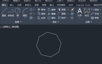
In CAD software, the three-dimensional drawing function allows designers to express design concepts more intuitively and create three-dimensional graphics. However, many users may not yet understand how to use CAD to draw three-dimensional graphics, so this article will introduce you in detail how to use CAD software to draw three-dimensional graphics to help you master this key skill. If you want to know more, please continue reading this article. I believe this tutorial guide will be helpful to you. Steps for drawing three-dimensional graphics in CAD: 1. Open the CAD2023 software and create a blank document. Create an 8-sided shape. As shown below: 2. Click the area tool in the drawing. Or enter a space after entering the REGION command. As shown below: 3. Select the object in REGION.
 How to merge a graphic after CAD rectangles are scattered
Feb 28, 2024 pm 12:10 PM
How to merge a graphic after CAD rectangles are scattered
Feb 28, 2024 pm 12:10 PM
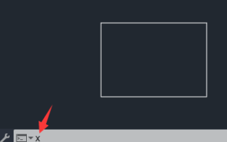
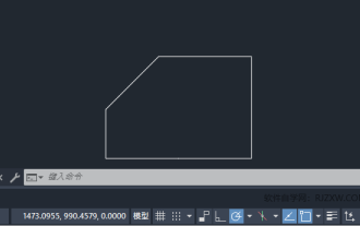
When using CAD software, we often encounter situations where we need to recombine "scattered" rectangular objects into a single graphic. This need arises in many fields, such as space planning, mechanical design and architectural drawings. In order to meet this demand, we need to understand and master some key functions in CAD software. Next, the editor of this website will introduce you in detail how to complete this task in the CAD environment. Users who have doubts can come and follow this article to learn. Method for merging CAD rectangles into one graphic after breaking them up: 1. Open the CAD2023 software, create a rectangle, and then enter the X command and a space. As shown below: 2. Select the rectangular object and space it. You can break up the objects. 3. Select all open lines
 How to set manual input dimensions for CAD annotation
Feb 27, 2024 pm 07:50 PM
How to set manual input dimensions for CAD annotation
Feb 27, 2024 pm 07:50 PM
CAD software is widely used in various design fields, and dimensioning is an indispensable part of CAD design. Sometimes, designers need to manually enter dimensions to ensure accuracy and flexibility. So this article will introduce in detail how to manually set and input dimensions in CAD. Users who don’t know how to set up manual input dimensions should come and learn along with this article! Steps for manually inputting size settings for CAD annotations: 1. Open the CAD2023 software, create a new blank document, and create a drawing, as shown below: 2. Then click the linear tool to create a linear annotation. As shown below: 3. Then click on both ends of the straight line to mark. As shown below: 4. Then enter T, or click the text (T) below, as shown below: 5. Hand
 binance official website URL Binance official website entrance latest genuine entrance
Dec 16, 2024 pm 06:15 PM
binance official website URL Binance official website entrance latest genuine entrance
Dec 16, 2024 pm 06:15 PM
This article focuses on the latest genuine entrances to Binance’s official website, including Binance Global’s official website, the US official website and the Academy’s official website. In addition, the article also provides detailed access steps, including using a trusted device, entering the correct URL, double-checking the website interface, verifying the website certificate, contacting customer support, etc., to ensure safe and reliable access to the Binance platform.
 What configuration is required to run CAD smoothly?
Jan 01, 2024 pm 07:17 PM
What configuration is required to run CAD smoothly?
Jan 01, 2024 pm 07:17 PM
What configurations are needed to use CAD smoothly? To use CAD software smoothly, you need to meet the following configuration requirements: Processor requirements: In order to run "Word Play Flowers" smoothly, you need to be equipped with at least one Intel Corei5 or AMD Ryzen5 or above processor. Of course, if you choose a higher-performance processor, you'll be able to get faster processing speeds and better performance. Memory is a very important component in the computer. It has a direct impact on the performance and user experience of the computer. Generally speaking, we recommend at least 8GB of memory, which can meet the needs of most daily use. However, for better performance and smoother usage experience, it is recommended to choose a memory configuration of 16GB or above. This ensures that the
 How to measure the area of graphics in CAD Viewer. How to measure the area of graphics in CAD Viewer.
Mar 13, 2024 pm 01:43 PM
How to measure the area of graphics in CAD Viewer. How to measure the area of graphics in CAD Viewer.
Mar 13, 2024 pm 01:43 PM
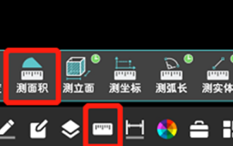
How to measure the area of graphics in CAD Viewer? CAD Viewer is a very easy-to-use software for viewing engineering drawings. This software has many functions, and drawings in various formats can be opened and viewed. If when we look at the drawings, we find that the area measurement of some graphics is wrong or that some graphics forget to measure the area, we can use this software to measure the area of the graphics. So how to measure the area of graphics? Below, the editor of this site has compiled a CAD drawing king's steps to measure the area of graphics for your reference. Steps for measuring the graphic area in CAD Viewer 1. First, open the drawing file in CAD Viewer APP, take the drawing with arc graphics as an example, and measure the area of the graphic. 2. After opening the drawing, go to the bottom of the software interface
 How to use CAD external reference? CAD external reference usage tutorial
Mar 04, 2024 pm 07:10 PM
How to use CAD external reference? CAD external reference usage tutorial
Mar 04, 2024 pm 07:10 PM
Do you know how to use cad external reference? Below, the editor brings how to use cad external reference. I hope it can be helpful to everyone. Let’s learn with the editor! How to use cad external reference? How to use cad external reference The first step of the tutorial: first open CAD and enter the XR command, as shown in the figure. Step 2: A prompt box will pop up. Click the icon to adhere the DWG above, as shown in the picture. Step 3: The selected file is a reference file, and the content in this file is used as a reference block and inserted into the current file, as shown in the figure. Step 4: Select the desired effect and the insertion is complete, as shown in the picture. The above is all the content on how to use cad external reference brought by the editor. I hope it can be helpful to everyone.
 How to use the cad stretch command-how to use the cad stretch command
Mar 06, 2024 pm 02:31 PM
How to use the cad stretch command-how to use the cad stretch command
Mar 06, 2024 pm 02:31 PM
Many novice friends still don’t know how to use the cad stretch command, so the editor below will bring you how to use the cad stretch command. Friends in need can quickly take a look. Step 1: Open the CAD software. For example, you want to stretch the triangle below, as shown in the picture below. Step 2: Enter the s shortcut key command in the command bar below and press Enter, as shown in the figure below. Step 3: Then select the object from right to left and press Enter (Note: It can neither be lower than the lower boundary nor exceed the upper vertex, and must be between the parts that need to be stretched.), as shown in the figure below. Step 4: Then specify the base point according to the prompts, as shown in the figure below. Step 5: Stretch to the specified position according to the drawing requirements and click to complete the stretching, as shown in the figure below. The above is the cad stretching instructions that the editor brings to you.