How to set the leader label
How to set leader labeling: First open the CAD software; then click the guide style management icon on the toolbar, and click the "New" button to enter the name of the new style; finally click "Continue", and Just set the "Text Style" attribute in the boot style modification interface.

The operating environment of this article: Windows 7 system, AutoCAD 2007, Dell G3 computer.
1. Click the boot style management icon on the toolbar. Or click [Format] → [Multi-Leader Style] to enter the management interface.
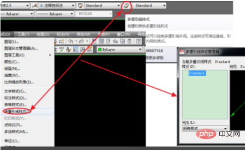
#2. Click the "New" button, enter the name of the new style in the pop-up dialog window, and then click "Continue".
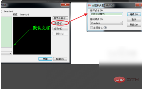
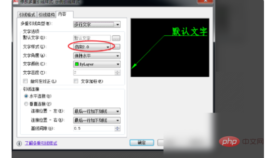
#3. Enter the boot style modification interface. The Content tab usually sets the Text Style property and selects the text style that has been set.
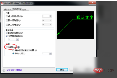
4. The "Main Structure" tab page is mainly for "Comments" inspection. Whether "Annotation" is selected, its function and application are similar to dimensions. Please refer to the introduction in label style settings quoted at the beginning of this article, which will not be repeated here.
5. In the "Lead Format" tab, focus on setting the symbol form and size of the "arrow". Usually set the "arrow" form: "closed entity", "point" and "none", see the next step for application.
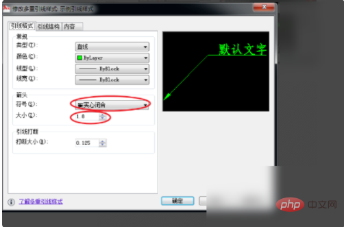
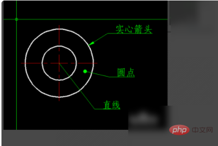
#6. "Solid closed" is usually used to point to the outline or corner of an entity. "Point" is usually used to point inside the outline of a solid. "None" is a straight line, usually pointing to another line, such as a dimension line, symmetry line, etc.
For more related articles, please visit the FAQ column!
The above is the detailed content of How to set the leader label. For more information, please follow other related articles on the PHP Chinese website!

Hot AI Tools

Undresser.AI Undress
AI-powered app for creating realistic nude photos

AI Clothes Remover
Online AI tool for removing clothes from photos.

Undress AI Tool
Undress images for free

Clothoff.io
AI clothes remover

AI Hentai Generator
Generate AI Hentai for free.

Hot Article

Hot Tools

Notepad++7.3.1
Easy-to-use and free code editor

SublimeText3 Chinese version
Chinese version, very easy to use

Zend Studio 13.0.1
Powerful PHP integrated development environment

Dreamweaver CS6
Visual web development tools

SublimeText3 Mac version
God-level code editing software (SublimeText3)

Hot Topics
 1374
1374
 52
52
 In-depth search deepseek official website entrance
Mar 12, 2025 pm 01:33 PM
At the beginning of 2025, domestic AI "deepseek" made a stunning debut! This free and open source AI model has a performance comparable to the official version of OpenAI's o1, and has been fully launched on the web side, APP and API, supporting multi-terminal use of iOS, Android and web versions. In-depth search of deepseek official website and usage guide: official website address: https://www.deepseek.com/Using steps for web version: Click the link above to enter deepseek official website. Click the "Start Conversation" button on the homepage. For the first use, you need to log in with your mobile phone verification code. After logging in, you can enter the dialogue interface. deepseek is powerful, can write code, read file, and create code
 deepseek web version official entrance
Mar 12, 2025 pm 01:42 PM
The domestic AI dark horse DeepSeek has risen strongly, shocking the global AI industry! This Chinese artificial intelligence company, which has only been established for a year and a half, has won wide praise from global users for its free and open source mockups, DeepSeek-V3 and DeepSeek-R1. DeepSeek-R1 is now fully launched, with performance comparable to the official version of OpenAIo1! You can experience its powerful functions on the web page, APP and API interface. Download method: Supports iOS and Android systems, users can download it through the app store; the web version has also been officially opened! DeepSeek web version official entrance: ht
 How to solve the problem of busy servers for deepseek
Mar 12, 2025 pm 01:39 PM
DeepSeek: How to deal with the popular AI that is congested with servers? As a hot AI in 2025, DeepSeek is free and open source and has a performance comparable to the official version of OpenAIo1, which shows its popularity. However, high concurrency also brings the problem of server busyness. This article will analyze the reasons and provide coping strategies. DeepSeek web version entrance: https://www.deepseek.com/DeepSeek server busy reason: High concurrent access: DeepSeek's free and powerful features attract a large number of users to use at the same time, resulting in excessive server load. Cyber Attack: It is reported that DeepSeek has an impact on the US financial industry.


