This article brings you relevant knowledge about Oracle, which mainly introduces issues related to the database architecture. The Oracle DB server consists of an Oracle DB and one or more database instances. The example consists of a memory structure and a background process. I hope it will be helpful to everyone.

Recommended tutorial: "Oracle Tutorial"
Oracle DB server consists of an Oracle DB and an Or multiple database instances. Instances consist of memory structures and background processes. Whenever an instance is launched, a shared memory area called the System Global Area (SGA) is allocated and background processes are started.
The database includes physical structure and logical structure. Since the physical and logical structures are separate, access to the logical storage structure is not affected when managing the physical storage of data. 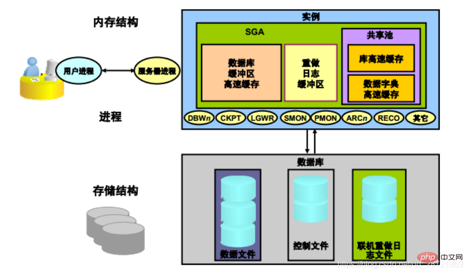
Oracle instances use memory structures and processes to manage and access databases. All memory structures exist in the main memory of those computers that make up the database server. Processes are jobs that run in the memory of these computers. A process is defined as a "thread of control" or mechanism in an operating system that runs a sequence of steps.
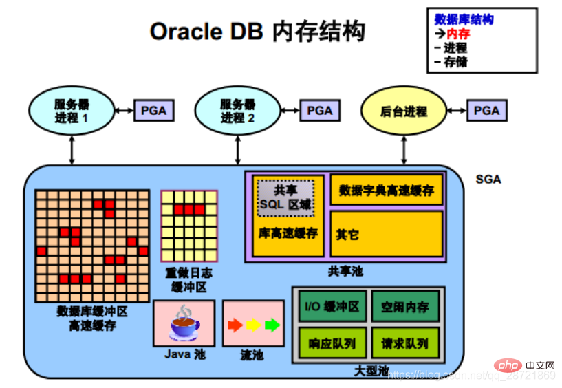
Oracle instances have two associated basic memory structures:
1. System Global Area (SGA)
is called the SGA component Groups of shared memory structures that contain data and control information for an Oracle DB instance. The SGA is shared by all servers and background processes. Examples of data stored in the SGA include cached data blocks and shared SQL areas.
SGA is the memory area that contains the data and control information of the instance. The SGA contains the following data structures:
• Database buffer cache: used to cache data blocks retrieved from the database
• Redo log buffer: used to cache redo information used for instance recovery until Can be written to physical redo log files stored on disk
• Shared pool: used to cache various structures that can be shared among users
• Large pool: used for certain large processes such as Oracle backup and Recovery operations) and I/O server processes provide optional areas of large memory allocations.
• Java Pool: Used for all session-specific Java code and data in the Java Virtual Machine (JVM)
• Stream Pool: Used by Oracle Streams to store the information needed to capture and apply operations
2. Program Global Area (PGA)
A memory area that contains data and control information for a server process or background process.
PGA is non-shared memory created by Oracle DB when the server process or background process starts. Server process access to the PGA is mutually exclusive. Each server process and background process has its own PGA.
The Program Global Area (PGA) is a memory area that contains data and control information for each server process. Oracle server processes service client requests. Each server process has its own dedicated PGA, which is created when the server process starts. Access to the PGA is limited to that server process and can only be read and written by Oracle code on behalf of that server process.
Oracle DB uses initialization parameters to create and manage memory structures. The simplest way to manage memory is to allow the database to automatically manage and optimize memory. To do this (the following works on most platforms), simply set the target memory size initialization parameter (MEMORY_TARGET) and the maximum memory size initialization parameter (MEMORY_MAX_TARGET).
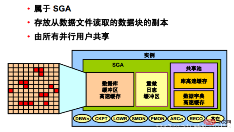
The database buffer cache is part of the SGA and is used to store copies of data blocks read from data files. All users connected to the instance in parallel share access to the database buffer cache.
The first time an Oracle DB user process requires a specific piece of data, it searches the database buffer cache for the data.
If the process finds the data in the cache (called a cache hit), the data is read directly from memory. If a process cannot find data in the cache (called a cache miss), the data block from the data file on disk must be copied to a buffer in the cache before the data can be accessed. Accessing data on a cache hit is faster than accessing data on a cache miss.
Buffers in the cache are managed by a complex algorithm that uses a combination of least recently used (LRU) lists and dock counting mechanisms.
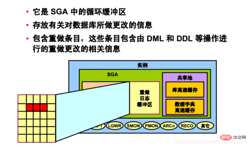
The redo log buffer is a circular buffer in SGA that stores information about changes made to the database. This information is stored in redo entries. Redo entries contain the information needed to rebuild (or redo) changes made to the database by DML, DDL, or internal operations. If necessary, redo entries will be used for database recovery.
When a server process changes the buffer cache, redo entries are generated and written to the redo log buffer in the SGA. Redo entries occupy contiguous sequential space in the buffer. The LGWR background process writes redo log buffers to active redo log files (or filegroups) on disk.
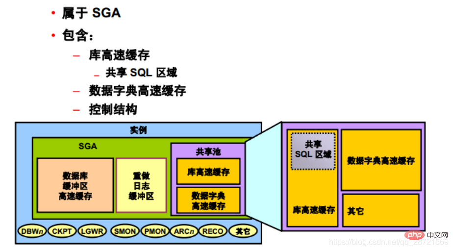
The shared pool part of SGA includes library cache, data dictionary cache, SQL query result cache, PL/SQL function result cache, parallelism Execution message buffers and control structures.
A "data dictionary" is a collection of database tables and views that contain reference information about a database, its structure, and its users. During SQL statement parsing, Oracle DB frequently accesses the data dictionary. This access operation is critical to the continued operation of Oracle DB.
Oracle DB accesses the data dictionary very frequently, so two special locations are designated in memory to store dictionary data.
An area is called the "data dictionary cache", also known as the "row cache" because it stores data in the form of rows rather than in the form of buffers (buffers are used to store complete data piece). Another area of memory used for dictionary data is called the "library cache." All Oracle DB user processes share these two caches for access to data dictionary information.
Oracle DB uses shared SQL regions (as well as private SQL regions reserved in the PGA) to represent each SQL statement it runs. Oracle DB recognizes when two users execute the same SQL statement and reuses the shared SQL region for those users.
The "Shared SQL Area" contains the parse tree and execution plan for a given SQL statement. Oracle DB saves memory by using a shared SQL region for SQL statements that are run multiple times. When many users run the same application, the same SQL statement is often run multiple times.
When a new SQL statement is parsed, Oracle DB allocates memory from the shared pool to store the statement in the shared SQL area. The size of this memory depends on the complexity of the statement.
Oracle DB handles PL/SQL program units (procedures, functions, packages, anonymous blocks, and data triggers) in much the same way it handles individual SQL statements. Oracle DB allocates a shared area to store the program unit in its parsed and compiled form. Oracle DB allocates a private area to store values specific to the session in which the program unit is running, including local variables, global variables, and package variables (also called "package instantiation"), and to store buffers used to execute SQL . If multiple users run the same program unit, all users use the same shared area but maintain separate copies of their own private SQL areas to hold values specific to their own sessions.
Individual SQL statements contained within a PL/SQL program unit are processed similarly to other SQL statements.
Regardless of the origin of these SQL statements in the PL/SQL program unit, they use a shared area to hold their parsing representation, and a dedicated area for each session in which the statement is run.
SQL query result cache and PL/SQL function result cache are new features in Oracle Database 11g.
They share the same infrastructure, appear in the same dynamic performance (V$) views, and are managed using the same provided packages.
The results of queries and query fragments can be cached in memory in the "SQL Query Results Cache". This way, the database can use the cached results to answer later executions of these queries and query fragments. Because retrieving results from the SQL query result cache is much faster than rerunning the query, caching the
results of frequently run queries can greatly improve the performance of these queries.
This function is sometimes used to return the results of a calculation if the input to the calculation is one or several parameterized queries issued by a PL/SQL function. In some cases, these queries access data that rarely changes (compared to how often the function is called).
You can include syntax in the source text of a PL/SQL function to request that the function results be cached in the "PL/SQL Function Results Cache" and that the cache be cleared when DML is encountered for a table in the table list (starting with Make sure it is correct).
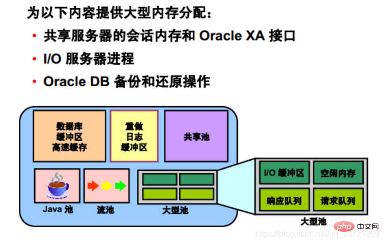
The database administrator can configure an optional memory area called a "large pool" to provide large memory allocations for:
• Shared servers Session memory and the Oracle XA or Parallel Query Buffer allocates session memory, Oracle DB can primarily use the shared pool to cache shared SQL and avoid the performance overhead caused by shrinking the shared SQL cache.
In addition, memory used for Oracle DB backup and restore operations, I/O server processes, and parallel buffers is allocated in buffers of hundreds of KB. Large pools serve such large memory requests better than shared pools.
There is no LRU list for large pools. It is different from reserved space in the shared pool, which uses the same LRU list as other memory allocated from the shared pool.
Java Pools and Stream Pools
The Java Pool Guidance statistics provide information about library cache memory for Java and predict how changes in Java pool size affect parsing rates. When statistics_level is set to TYPICAL or higher, Java pool guidance is turned on internally. These statistics will be reset when you close the guide. 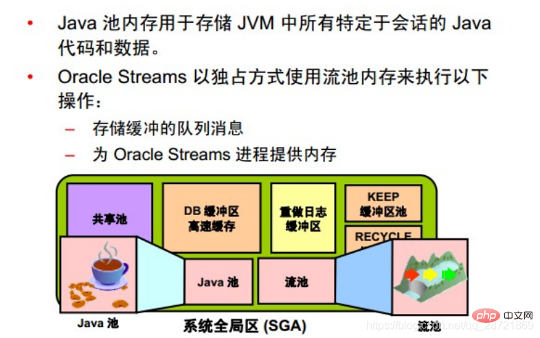 The stream pool is used exclusively by Oracle Streams. The stream pool stores buffered queue messages and provides memory for Oracle Streams capture processes and application processes.
Unless the stream pool is specially configured, its size starts at zero. When using Oracle Streams, the pool size grows dynamically as needed.
Program Global Area (PGA)
Each PGA contains stack space. In a dedicated server environment, there is a separate server process for each user who connects to the database instance. For this type of connection, the PGA contains a subdivision of memory called the User Global Area (UGA). UGA includes the following parts: 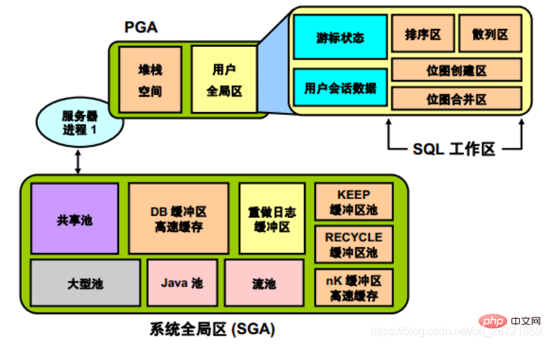 • Cursor area, used to store runtime information of the cursor
• User session data storage area, used to store control information about the session
• SQL workspace, used to process SQL Statements, including:
The processes in the Oracle DB system are mainly divided into two groups:
1. User processes that run applications or Oracle tool codes
For different Oracle DB configuration, user process structure varies depending on the operating system and OracleDB options selected. Code for connected users can be configured as a dedicated server or a shared server.
• Dedicated Server: For each user, the user process running the database application is served by a dedicated server process that executes the Oracle DB server code.
• Shared Server: It is not necessary to have a dedicated server process for each connection. The dispatcher directs multiple incoming network session requests to the shared server process pool. The shared server process services all client requests.
2. Oracle DB process running Oracle DB server code (including server process and background process)
2.1. Server process
Oracle DB creates a server process to handle requests from user processes connected to the instance. User processes represent applications or tools that connect to Oracle DB. It can be on the same computer as Oracle DB, or it can be on a remote client using the network to access Oracle DB. The user process first communicates with a listener process, which in a dedicated environment creates a server process.
The server process created on behalf of each user's application can do one or more of the following:
• Parse and run SQL statements issued through the application
• From disk Read the necessary data blocks from the data file on the SGA into the SGA's shared database buffer (if they are not already in the SGA)
• Return the results so that the application can process the information
2.2. Background processes
In order to maximize performance and meet the needs of multiple users, multi-process Oracle DB systems use some additional Oracle DB processes called "background processes". An Oracle DB instance can have multiple background processes.
Common background processes in non-RAC, non-ASM environments include:
• Database write process (DBWn)
• Log write process (LGWR)
• Checkpoint process (CKPT)
• System Monitor Process (SMON)
• Process Monitor Process (PMON)
• Restorer Process (RECO)
• Job Queue Coordinator (CJQ0)
• Job Slave Process (Jnnn)
• Archive Process (ARCn)
• Queue Monitor Process (QMNn)
There may be other background processes in more advanced configurations (such as RAC). For more information about background processes, see the V$BGPROCESS view.
Some background processes are automatically created when starting an instance, while others are created on demand.
Other process structures are not specific to a single database, but can be shared among multiple databases on the same server. Grid Infrastructure processes and network processes fall into this category.
Oracle Grid Infrastructure processes on Linux and UNIX systems include:
• ohasd: Oracle High Availability Service Daemon, responsible for starting the Oracle Clusterware process
• ocssd: Cluster Synchronization Service Daemon
• diskmon: Disk monitoring daemon, responsible for monitoring input and output of HP Oracle Exadata Storage Server
• cssdagent: Start, stop, and check the status of the CSS daemon ocssd
• oraagent: Extend clusterware to support Oracle-specific requirements and complexities Resources
• orarootagent: A specialized Oracle agent process that helps manage resources (such as networks) owned by the root user 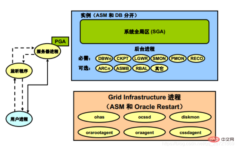
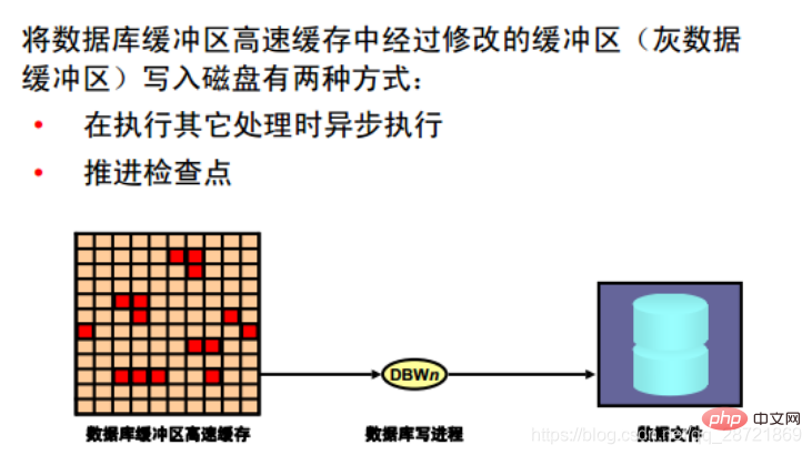
The database write process (DBWn) can write the contents of the buffer to the data file. The DBWn process is responsible for writing modified buffers (gray data buffers) in the database buffer cache to disk. Although for most systems, one database write process (DBW0) is sufficient; however, if the system requires frequent modification of data, additional processes (DBW1 to DBW9 and DBWa to DBWz) can be configured to improve write performance. These additional DBWn processes are not useful on uniprocessor systems.
When a buffer in the database buffer cache is modified, the system marks it as a gray data buffer and adds it to the head of the checkpoint queue in SCN order. Therefore, the order is consistent with the order in which the redo entries for these changed buffers are written to the redo log. When the number of free buffers in the buffer cache falls below some internal threshold (to the point where the server process considers it difficult to obtain free buffers), DBWn writes infrequently used buffers to the data file, writing The ordering starts at the end of the LRU list, allowing processes to replace buffers as they are needed. DBWn also writes from the tail of the checkpoint queue to protect checkpoints moving forward.
There is a memory structure in the SGA that holds the redo byte address (RBA) of the location in the redo stream from which recovery will begin when an instance fails. This structure serves as a pointer to redo and is written to the control file by the CKPT process once every three seconds. Since DBWn writes the gray data buffer in SCN order, and redo is performed in SCN order, whenever DBWn writes the gray data buffer from the LRUW list, the pointer held in the SGA memory structure will also be moved forward to facilitate instance recovery. (If necessary) Start read redo from approximately the correct position and avoid unnecessary I/O. This is called an "incremental checkpoint".
Note: There are other situations in which DBWn may perform write operations (for example, when the table space is set to read-only or placed offline). In these cases, incremental checkpoints do not occur because the order in which the gray data buffers belonging only to the corresponding data files are written to the database is independent of the SCN order.
The LRU algorithm keeps more frequently accessed blocks in the buffer cache to minimize disk reads. You can use the CACHE option with a table to help keep blocks in memory longer.
The DB_WRITER_PROCESSES initialization parameter specifies the number of DBWn processes. The maximum number of DBWn processes is 36. If the user does not specify this number of processes during startup, Oracle DB will determine how to set DB_WRITER_PROCESSES based on the number of CPUs and processor groups.
The DBWn process writes gray data buffers to disk under the following conditions:
• When the server process cannot find a clean reusable buffer after scanning a threshold number of buffers, DBWn is notified to perform a write operate. DBWn writes the gray data buffer to disk asynchronously while performing other processing.
• DBWn write buffer to advance the checkpoint. A checkpoint is the starting position in the redo thread (log) used to perform instance recovery. The log position is determined by the oldest gray data buffer in the buffer cache. In all cases, DBWn performs batched (multi-block) write operations to improve efficiency. The number of blocks written in a multi-block write operation varies depending on the operating system.
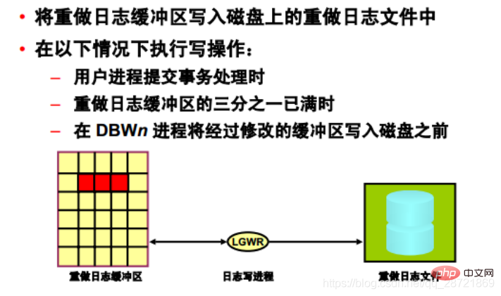
The Log Write Process (LGWR) is responsible for managing the redo log buffer by writing redo log buffer entries to the redo log buffer on disk. Make log files. LGWR writes all redo entries copied into the buffer since the last write.
The redo log buffer is a circular buffer. After LGWR writes the redo entries in the redo log buffer to the redo log file, the server process can copy the new entries into the redo log buffer on top of those that have been written to disk. LGWR's write speed is usually fast enough to ensure that there is always room in the buffer for new entries, even when access to the redo log is heavy. LGWR writes a contiguous portion of the buffer to disk.
LGWR performs write operations under the following circumstances:
• When a user process commits a transaction
• When one-third of the redo log buffer is full
• When the DBWn process transfers a modified Before the buffer is written to disk (if necessary)
• Every 3 seconds
All redo records associated with the buffer changes must be written to disk before DBWn can write the modified buffer to disk District (write the agreement first). If DBWn discovers that some redo records have not yet been written, it notifies LGWR
to write these redo records to disk and waits for LGWR to complete writing the redo log buffer before writing to the data buffer. LGWR will write to the current log group. If a file in the group becomes corrupted or unavailable, LGWR will continue writing to other files in the group and log an error in the LGWR trace file and system alert log. If all files in a group are corrupted, or the group is unavailable because it has not been archived, LGWR cannot continue to work.
When the user issues a COMMIT statement, LGWR will place a commit record in the redo log buffer and immediately write the record to disk along with the transaction's redo log. Corresponding changes to the data blocks are delayed until they can be written more efficiently. This is called the "fast commit mechanism". An atomic write of a redo entry that contains a transaction commit record is a single event that determines whether a transaction has committed.
Oracle DB returns a success code for a committed transaction even though the data buffer has not yet been written to disk.
If more buffer space is needed, LGWR sometimes writes redo log entries before committing the transaction. These entries become permanent only if the transaction is later committed. When a user commits a transaction, the transaction is assigned a system change number (SCN), which Oracle DB records in the redo log along with the transaction's redo entries. SCNs are recorded in the redo log so that recovery operations can be synchronized between Real Application Clusters and distributed
databases.
When activity is high, LGWR can write redo log files by using group commit. For example, assume a user submits a transaction. LGWR must write the redo entries for this transaction to disk. When this happens, other users will issue COMMIT statements. However, LGWR cannot write to the redo log files to commit these transactions until it completes its previous write operation. After the first transaction's entries are written to the redo log file, the entire list of redo entries for pending (not yet committed) transactions can be written to disk in a single operation, which is faster than processing individual transaction entries individually. Less I/O is required. As a result, Oracle DB can minimize disk I/O and maximize the performance of LGWR. If the rate of commit requests is consistently high, each write operation from the redo log buffer (performed by LGWR) may contain multiple commit records.
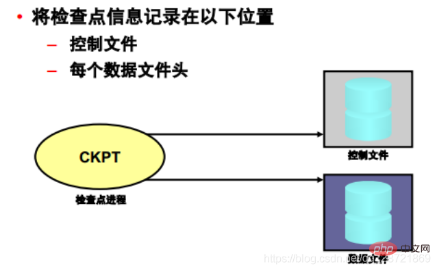
A "checkpoint" is a data structure that defines a system change number (SCN) in the redo thread of a database . Checkpoints are recorded in the control file and in the header of each data file. They are critical elements of recovery operations.
When a checkpoint occurs, Oracle DB must update the headers of all data files to record the details of the checkpoint. This is done by the CKPT process. The CKPT process does not write blocks to disk; that work is performed by DBWn. The SCN recorded in the file header guarantees that all changes to the database blocks prior to that SCN are written to disk.
The SYSTEM_STATISTICS monitor in Oracle Enterprise Manager displays statistics DBWR checkpoints indicating the number of completed checkpoint requests.

The System Monitor Process (SMON) performs recovery when the instance starts (if needed). SMON is also responsible for cleaning up temporary segments that are no longer in use. If any terminated transactions are skipped during instance recovery due to file read or offline errors, SMON will resume those transactions when the table space or file comes back online.
SMON checks periodically to see if the process is needed. Other processes can also call it when they detect the need for SMON.
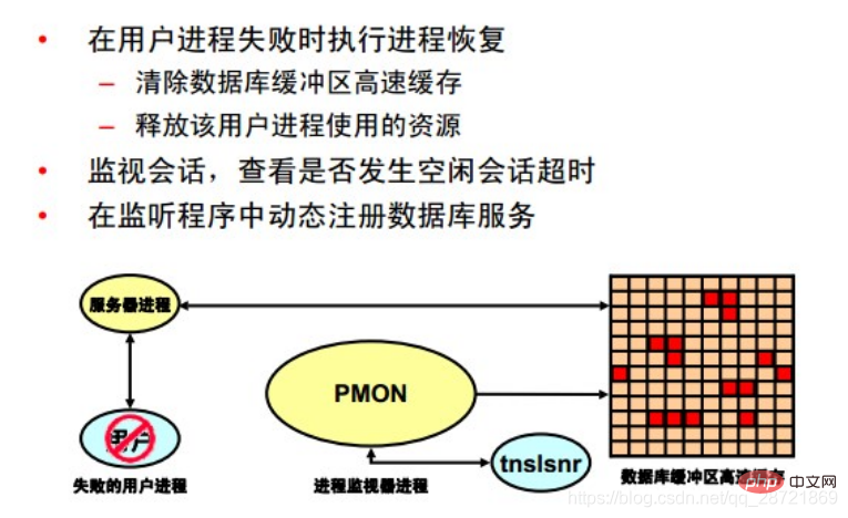
The Process Monitor Process (PMON) performs process recovery when a user process fails. PMON is responsible for clearing the database buffer cache and releasing resources occupied by the user process. For example, PMON resets the state of active transaction tables, releases locks, and removes the process ID from the list of active processes.
PMON periodically checks the status of dispatcher and server processes and restarts any dispatcher and server processes that have stopped running (unless intentionally terminated by OracleDB). PMON also registers information about the instance and dispatcher processes with the network listener.
Like SMON, PMON checks periodically to see if it needs to run; it can also be called by other processes if it detects that it is needed.
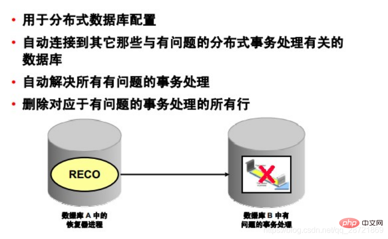
The restorer process (RECO) is a background process used in distributed database configurations to automatically resolve failures involving distributed transaction processing. The instance's RECO process automatically connects to other databases that are involved in the distributed transaction processing in question. When the RECO process reestablishes connections between the involved database servers, it automatically resolves all problematic transactions and removes from each database's pending transactions table all transactions corresponding to the resolved problematic transactions. OK.
If the RECO process cannot connect to the remote server, RECO will automatically try to reconnect after a certain time interval. However, RECO will wait an increasing amount of time (exponentially) before retrying to connect.
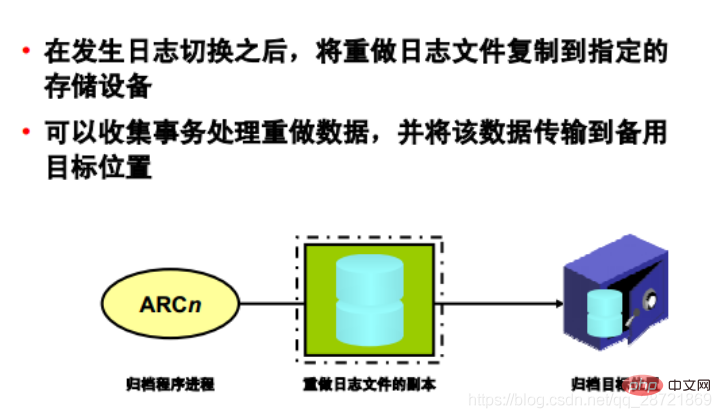
After a log switch occurs, the archiving process (ARCn) copies the redo log files to the specified storage device. The ARCn process only exists when the database is in ARCHIVELOG mode and automatic archiving is enabled.
If you anticipate a heavy archiving workload (such as during batch loading of data), you can increase the maximum number of archive processes using the LOG_ARCHIVE_MAX_PROCESSES initialization parameter. The ALTER SYSTEM statement can dynamically change the value of this parameter to increase or decrease the number of ARCn processes.
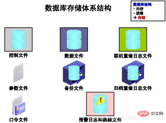
The files that make up Oracle DB can be divided into the following categories:
• Control files: Contains data related to the database itself, i.e. Physical database structure information. These files are critical to the database. Without these files, the data files cannot be opened to access the data in the database.
• Data files: Contains the user or application data of the database, as well as metadata and data dictionary
• Online redo log files: Used for instance recovery of the database. If the database server crashes but no data files are lost, the instance can use the information in these files to recover the database.
The following additional files are important to successfully run the database:
• Parameter file: used to define the configuration when the instance is started
• Password file: allows sysdba, sysoper, and sysasm to connect to the instance remotely and perform administrative tasks
• Backup file: used for database recovery. Backup files are typically restored if the original files were damaged or deleted due to media failure or user error.
• Archived redo log files: Contains a real-time history of data changes (redos) that occurred on an instance. Using these file and database backups, lost data files can be recovered. In other words, archive logs can restore restored data files.
• Trace files: Each server and background process can write to associated trace files. When a process detects an internal error, the process dumps information about the error into the appropriate trace file. Some of the information written to the trace file is provided for the database administrator, while other information is provided for Oracle Support Services.
• Alert log files: These files contain special trace entries. The database's warning log is a message log and error log listed in chronological order. Oracle recommends that you review the alert log periodically.
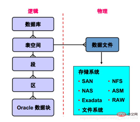
This slide explains the relationship between database, tablespace and data file The relationship is explained. Each database is logically divided into two or more table spaces. One or more data files are explicitly created in each table space to physically store the data of all logical structures in the table space. For TEMPORARY tablespaces, no data files are created, but temporary
files are created. Table space data files can be physically stored using any supported storage technology.
The database is divided into multiple logical storage units, called "table spaces", which are used to group related logical structures or data files. For example, table spaces typically group all segments of an application into one group to simplify some management operations. 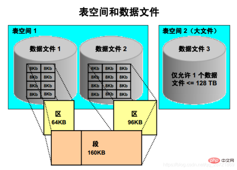
A database is divided into "table spaces", which are logical storage units that can be used to group related logical structures together. Each database is logically divided into two or more table spaces: SYSTEM and SYSAUX table spaces. One or more data files are explicitly created in each table space to physically store the data of all logical structures in the table space.
A segment of size 160 KB spans two data files and consists of two extents. The first extent is located in the first data file and is 64 KB in size; the second extent is located in the second data file and is 96 KB in size. Both extents consist of several contiguous 8Kb Oracle blocks.
Note: It is possible to create a large file table space, which has only one file, which is usually very large. The file can be up to the maximum size allowed by the row ID architecture. This maximum size is the block size of the table space multiplied by 236, or if the block size is 32 KB, the maximum size is 128 TB. A traditional small file tablespace (the default) can contain multiple data files, but these files are not very large.
Oracle DB data is stored in "data blocks", which are the lowest level of granularity. A data block corresponds to a specific number of bytes of physical space on disk. The data block size of each table space is specified when the table space is created. The database uses and allocates free database space in units of Oracle data blocks.

The next level of the logical database space is the "district". An extent is a specific number of contiguous blocks of Oracle data (obtained from a single allocation) used to store a specific type of information. Oracle data blocks within an extent are logically contiguous, but can be physically spread out in different locations on the disk (RAID striping and file system implementations can cause this behavior).
The upper level of the logical database storage area is called a "segment". A segment is a set of areas allocated for a certain logical structure. For example:
• Data Segment: Each non-clustered, non-index-organized table has a data segment, except external tables, global temporary tables, and partitioned tables, each of which has one or Multiple segments. All data in the table is stored in the extent of the corresponding data segment. For partitioned tables, there is one data segment for each partition. Each cluster also has a data segment. Data for each table in the cluster is stored in the cluster's data segment.
• Index segment: Each index has an index segment that stores all its data. For a partitioned index, there is one index segment for each partition.
• Undo segment: The system creates an UNDO tablespace for each database instance. This tablespace contains a large number of restore segments that are used to temporarily store restore information. The information in the restore segment is used to generate read-consistent database information to roll back user uncommitted transactions during database recovery.
• Temporary Segments: Temporary segments are created by Oracle DB when a SQL statement requires a temporary work area to complete execution. After the statement completes execution, the temporary segment's extent is returned to the instance for future use. You can specify a default temporary table space for each user, or specify a default temporary table space that is used within the scope of the database.
Note: There are also some other types of segments not listed above. In addition, there are some schema objects, such as views, packages, and triggers, which are not considered segments although they are database objects. Segments have separate allocations of disk space. Other objects are stored as rows in the system metadata segment.
Oracle DB server dynamically allocates space. If the existing extents in the segment are full, additional extents are added. Because extents are allocated as needed, the extents in a segment may or may not be adjacent on disk, and they may come from different data files belonging to the same table space.
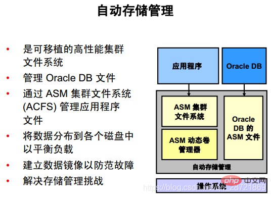
Automatic Storage Management (ASM) provides file system and volume manager vertical integration for Oracle DB files. ASM can manage a single symmetric multiprocessing (SMP) computer, or multiple nodes of a cluster to support Oracle Real Application Clusters (RAC).
Oracle ASM Cluster File System (ACFS) is a multi-platform, scalable file system and storage management technology that extends the functionality of ASM to support application files external to Oracle DB, such as executable files, Reports, BFILEs, video, audio, text, images, and other general-purpose application file data.
ASM distributes input/output (I/O) load across all available resources, both eliminating manual optimization of I/O and optimizing performance. ASM helps DBAs manage dynamic database environments by allowing DBAs to adjust storage allocations by increasing the size of the database without shutting down the database.
ASM can maintain redundant copies of data to provide fault tolerance, or it can be built on top of vendor-provided storage mechanisms. Data management is achieved by selecting the required reliability and performance metrics for each type of data, rather than manual interaction on a file-by-file basis.
ASM capabilities save DBAs time by automating manual storage tasks, thereby increasing administrators' ability to manage more and larger databases more efficiently. 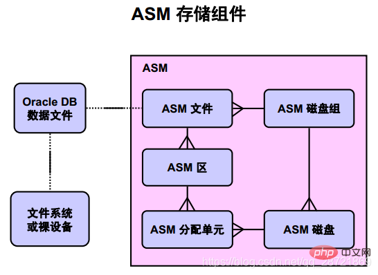
ASM does not hinder any existing database functionality. Existing databases can work as usual. New files can be created as ASM files, and existing files can be managed as-is or migrated to ASM.
The above diagram illustrates the relationship between Oracle DB data files and ASM storage components. The crow's foot mark represents a one-to-many relationship. There is a one-to-one relationship between Oracle DB data files and files or ASM files stored in the operating system's file system.
An Oracle ASM disk group is a collection of one or more Oracle ASM disks that are managed as a logical unit. The data structures in the disk group are self-contained and use part of the space for metadata needs. Oracle ASM disk is a storage device provisioned for Oracle ASM disk group, which can be a physical disk, a partition, a
logical unit number (LUN) in a storage array, a logical volume (LV), or a file connected to the network . Each ASM disk is divided into a number of ASM allocation units (AU), which is the smallest amount of contiguous disk space that ASM can allocate. When you create an ASM disk group, you can set the ASM allocation unit size to 1, 2, 4, 8, 16, 32, or 64 MB, depending on the compatibility level of the disk group. One or more ASM allocation units form an ASM region. Oracle ASM areas are raw storage used to store the contents of Oracle ASM files. Oracle ASM files consist of one or more file extents. To support very large ASM files, variable size extents can be used, with extent sizes equal to 1x, 4x, and 16x the AU size.
Recommended tutorial: "Oracle Video Tutorial"
The above is the detailed content of Detailed graphic explanation of oracle database architecture. For more information, please follow other related articles on the PHP Chinese website!