

How can self-driving car lidar be synchronized with GPS time?

Among the five messages defined by gPTP, Sync and Follow_UP are a group of messages, which are sent periodically and are mainly used to measure clock deviation.
01 Synchronization scheme
There are three main schemes for laser radar and GPS time synchronization, namely PPS GPRMC, PTP, gPTP
PPS GPRMC
GNSS output two One piece of information is a synchronization pulse signal PPS with a time period of 1s and a pulse width of 5ms~100ms; the other is a GPRMC standard time synchronization message output through a standard serial port.
The synchronization pulse leading edge moment is at the same moment as the GPRMC message is sent, the error is ns level, and the error can be ignored. GPRMC is a standard format message containing UTC time (accurate to seconds), longitude and latitude positioning data.

PPS second pulse is a physical level output. The time for receiving and processing the PPS signal is at the ns level and can still be ignored. However, GPRMC data is generally sent through a serial port with a baud rate of 9600. The sending, receiving, and processing time tx is at the ms level, which is the key to time synchronization.
The following is the principle of using PPS GPRMC for time synchronization.
(1) After the device receives the PPS second pulse signal, it clears the milliseconds and below in the internal system time with the crystal oscillator as the clock source, and starts calculating the millisecond time from this.
(2) After receiving the GPRMC data, extract the hour, minute, second, year, month, and day UTC time in the message.
(3) Add the time tx from receiving the second pulse to parsing the UTC time in GPRMC to the UTC whole second time, and synchronize it to the system time. So far, a time synchronization has been completed. Repeat the same process for the next second, calibrating exactly once every second.
Smart people may have suddenly realized that lidar needs to be time synchronized. Just make two wires and connect them to these two physical interfaces. This method is possible and is also a solution used by many manufacturers. , but PPS GPRMC has the following problems.
(1) PPS is a low-power pulse level signal. The driving current is as little as 0.5mA and as much as 20mA, with several synchronization nodes (lidar and other nodes that require time synchronization) , a dozen or so would be very difficult.
(2) PPS is an unshielded single-line pulse signal. More than a dozen PPS lines shuttle in the car, which is extremely susceptible to interference from the harsh electromagnetic environment in the car. It will be impossible to distinguish whether it is an interference pulse or a synchronization pulse. .
(3) GPRMC sends synchronization messages through the RS232 serial port. RS232 is a 1-to-1 full-duplex communication form, and can also achieve 1-to-several data transmission in a master-slave form. But for more than ten people, it is really rare, and it can only be verified through experiments whether it is feasible. But at least the wiring harness engineer was unwilling to agree.
(4) When the clock source is lost, all the equipment that needs time synchronization suddenly loses its backbone. Each junior can stand on his own, and there is no second leader to stand up in time and take charge of the overall situation. This is simply unacceptable for autonomous driving systems with extremely high functional safety requirements.
PTP
Therefore, it is theoretically feasible to achieve time synchronization of the entire autonomous driving system based on simple PPS and GPRMC, but it is not practical.
The network-based high-precision time synchronization protocol PTP (Precision Time Protocol, 1588 V2) can achieve sub-microsecond synchronization accuracy. For a global architecture where the backbone network is Ethernet, everything is ready. It only needs the support of the hardware PHY chips of each domain controller.
PTP is a master-slave time synchronization system that uses hardware timestamps, so it can significantly reduce software processing time. At the same time, PTP can run on the L2 layer (MAC layer) and L4 layer (UDP layer). When running on the L2 layer network, packet parsing is performed directly on the MAC layer without going through the four-layer UDP protocol stack, thus greatly reducing the protocol stack residency. time, further improving time synchronization accuracy, which is very friendly to autonomous driving systems.
An architectural solution under the global architecture is as shown below.
The network port running the PTP protocol in the device is called the PTP port. The PTP master port is used to publish the time, and the PTP slave port is used to receive the time. Three types of clock nodes are defined at the same time, boundary clock node (BC, Boundary Clock), ordinary clock node (OC, Ordinary Clock) and transparent clock node (TC, Transparent clock).
(1) The boundary clock node has multiple PTP ports, one of which is used to synchronize the time of the upstream device, and the remaining ports are used to send time to the downstream device. When the upstream time synchronization device of the boundary clock node is a GNSS receiver, the boundary clock node at this time is a master clock node (optimal clock).
(2) Ordinary clock nodes have only one PTP port, which is used to synchronize the time of the upstream clock node.
(3) Transparent clock, as its name suggests, has multiple PTP ports, what time is received, what time is forwarded, does not perform protocol analysis, and does not participate in time synchronization internally. PTP exchanges synchronization messages between the master and slave devices and records the message sending time to calculate the network transmission delay and the clock deviation between the master and slave devices.
PTP defines four synchronization messages: Sync, Follow_Up, Delay_Req, and Delay_Resp. The precise synchronization process is as follows.

(1) The PTP master port sends a Sync message to the slave port, and the Sync sending time t1 is synchronously recorded. After receiving the Sync message from the port, the reception time t2 is recorded.
(2) Then the master port puts the t1 time in the Follow_Up message and sends it to the slave port. After receiving this message, the slave port can parse out t1 and get the first equation: t1 Network delay clock deviation = t2.
(3) The slave port sends a Delay_Req message to the master port, and simultaneously records the time t3 when the Delay_Req is sent. After the main port receives the message, it records the time t4 when it was received.
(4) Then the master port puts the t4 time in the Delay_Resp message and sends it to the slave port. After receiving this message, the slave port can parse out t4 and get the first equation: t3 Network delay-clock deviation=t4. Two unknowns and two systems of equations can be solved by applying junior high school mathematics knowledge: network delay = [(t2-t1) (t4-t1)]/2, clock deviation = [(t2-t1)-(t4-t3 )]/2.
gPTP
gPTP (generalized Precision Time Protocol), a series of optimizations based on the PTP (IEEE 1588v2) protocol, has formed a more targeted time synchronization mechanism , which can achieve μs-level synchronization accuracy.
gPTP defines two device types, Time-aware-end Station and Time-aware Bridge. Each device has a local clock. The local clock is measured by the oscillation period of the crystal oscillator. The internal hardware counter of the device is responsible for counting the oscillation period. The network port on the device used to publish time synchronization messages is called the master port, and the port used to receive time synchronization messages is called the slave port.
(1) Time-aware-end Station, which can be used as either a master clock or a slave clock.
(2) Time-aware Bridge can be used as either a master clock or a bridge device, similar to a switch. After receiving the gPTP message, the bridge device will give the message a bath before sending it out. The time consumed by the message in the bridge device is called the dwell time. gPTP requires that the bridge device must have the ability to measure dwell time.
The following figure shows a simple gPTP system, including a clock source, 1 master clock, 2 bridge devices, and 4 slave clocks. The master clock is the time base within the system. It generally has a higher-precision local clock and needs to be timed by a high-precision quasi-clock source. The master clock can be dynamically allocated within the system or pre-allocated (for vehicle-mounted fixed topology application scenarios, the principle of pre-allocation is often used).

The master clock dynamic allocation mechanism specified in gPTP is BMCA (Best Master Clock Algorithm, best master clock selection algorithm). After the system is powered on and wakes up, all devices in the system can participate in the master clock election by sending a message, which contains the clock information of their respective devices. Each participating device will compare its own clock information with the clock information of other devices and determine whether it has an advantage. If not, it will withdraw from the election until the martial arts leader with the strongest comprehensive ability is born.
02 Synchronization process
gPTP defines two types of messages, event type messages (including Sync, Pdelay_Req, and Pdelay_Resp) and general type messages (including Follow_UP and Pdelay_Resp_Follow_UP). gPTP defines that the device works in the MAC (Media Acess Control) sublayer of the second data link layer in the seven-layer network model.
When the device MAC layer receives or sends an event type message, it will trigger the sampling of the hardware counter to obtain the clock oscillation cycle count value. Combined with the clock oscillation frequency and the reference time, the timestamp at this time can be obtained . General type messages are only used to carry information and will not trigger the sampling operation of the internal hardware counter.
Clock deviation measurement
Among the five messages defined by gPTP, Sync and Follow_UP are a group of messages, which are sent periodically and are mainly used to measure clock deviation. Sync is sent by the main port. When the message leaves the MAC layer of the main port, the main port is triggered to record the timestamp t1 at this time. After receiving the Sync message from the port MAC layer, the timestamp t2 at this time is recorded. Subsequently, the master port attaches the t1 value to the Follow_UP message and sends it to the slave port.

If there is no network transmission delay or delay, which can be ignored, the slave port will add the local clock value to the clock offset (the value of t1-t2) to complete the time synchronization, that is, There are no further thoughts behind it. However, for gPTP with μs-level time synchronization accuracy, transmission delay obviously cannot be ignored.
Transmission delay measurement
gPTP uses the P2P (Peer to Peer) method to measure transmission delay. In the P2P method, the transmission delay between adjacent devices is measured, and messages are not allowed to be transmitted across devices. This requires that all devices in the gPTP network need to support the gPTP function. At the same time, a set of independent messages is defined specifically for transmission delay measurement, which are Pdelay_Req, Pdelay_Resp and Pdelay_Resp_Follow_UP that are sent periodically.

The slave port first sends a Pdelay_Req message, marking the beginning of the transmission delay measurement. When the message leaves the MAC layer of the slave port, the slave port is triggered to record the timestamp t3 at this time. . After receiving the Pdelay_Req message, the MAC layer of the master port will record the timestamp t4 at this time. Then, the master port sends the value t4 to the slave port through the Pdelay_Resp message. At the same time, when the Pdelay_Resp message leaves the MAC layer of the master port, the master port triggers The port records the timestamp t5 at this time, and records the timestamp t6 at this time after receiving the Pdelay_Resp message from the port MAC layer. Subsequently, in the same routine, the master port sends the value t5 to the slave port through the Pdelay_Resp_Follow_Up message. At this point, a transmission delay measurement process has ended. Assuming that the path transmission delay is symmetrical, the transmission delay between adjacent devices can be calculated according to the following formula.

Frequency synchronization
The above transmission delay measurement is based on the premise that the clock oscillation frequency of the slave port and the master port is consistent. Now let's consider what supernatural events will occur if the oscillation frequencies of the master and slave port clocks are inconsistent. Assuming that the clock oscillation frequency of the slave port is 25MHz, one clock oscillation period is 40ns. The clock oscillation frequency of the master port is 100MHz, and the clock oscillation period of one clock is 10ns.
Assume that during a transmission delay measurement process, the difference between the oscillation periods recorded by the slave port at t6 and t3 is 200 oscillation periods. Since the clock frequency of the master port is 4 times that of the slave port, the slave port receives about 800 oscillation period differences between t5 and t4. If calculated based on the 40ns clock oscillation period of the slave port, the transmission delay is -24μs ([200x40-800x40]/2). Not only is there no delay in transmission, but it is known in advance, and there is no doubt about it from the port.
In addition to the inherent inconsistency in the clock oscillation frequency of the master and slave ports, factors such as temperature and aging can also cause instability in the crystal oscillator frequency. In order to solve the problem of frequency synchronization, gPTP uses frequency synchronization to synchronize the clock oscillation frequency of the slave port to the master port.

Frequency synchronous multiplexing transmits the Pdelay_Resp and Pdelay_Resp_Follow_UP messages of the delay measurement process. By using two sets of responses, the values of t5, t6, t9, and t10 can finally be obtained. The frequency ratio of the master-slave port can be obtained from the following formula.

When the master-slave port frequency is synchronized, the frequency ratio is equal to 1. If it is greater than 1, it means that the main port is running fast; if it is less than 1, it means that the main port is running slowly. The slave port adjusts its time base according to the value of the frequency ratio to obtain the correct timestamp.
The above is the detailed content of How can self-driving car lidar be synchronized with GPS time?. For more information, please follow other related articles on the PHP Chinese website!

Hot AI Tools

Undresser.AI Undress
AI-powered app for creating realistic nude photos

AI Clothes Remover
Online AI tool for removing clothes from photos.

Undress AI Tool
Undress images for free

Clothoff.io
AI clothes remover

AI Hentai Generator
Generate AI Hentai for free.

Hot Article
Hot Tools

Notepad++7.3.1
Easy-to-use and free code editor

SublimeText3 Chinese version
Chinese version, very easy to use

Zend Studio 13.0.1
Powerful PHP integrated development environment

Dreamweaver CS6
Visual web development tools

SublimeText3 Mac version
God-level code editing software (SublimeText3)
Hot Topics
 1378
1378
 52
52

 Why is Gaussian Splatting so popular in autonomous driving that NeRF is starting to be abandoned?
Jan 17, 2024 pm 02:57 PM
Why is Gaussian Splatting so popular in autonomous driving that NeRF is starting to be abandoned?
Jan 17, 2024 pm 02:57 PM
Written above & the author’s personal understanding Three-dimensional Gaussiansplatting (3DGS) is a transformative technology that has emerged in the fields of explicit radiation fields and computer graphics in recent years. This innovative method is characterized by the use of millions of 3D Gaussians, which is very different from the neural radiation field (NeRF) method, which mainly uses an implicit coordinate-based model to map spatial coordinates to pixel values. With its explicit scene representation and differentiable rendering algorithms, 3DGS not only guarantees real-time rendering capabilities, but also introduces an unprecedented level of control and scene editing. This positions 3DGS as a potential game-changer for next-generation 3D reconstruction and representation. To this end, we provide a systematic overview of the latest developments and concerns in the field of 3DGS for the first time.
 How to solve the long tail problem in autonomous driving scenarios?
Jun 02, 2024 pm 02:44 PM
How to solve the long tail problem in autonomous driving scenarios?
Jun 02, 2024 pm 02:44 PM
Yesterday during the interview, I was asked whether I had done any long-tail related questions, so I thought I would give a brief summary. The long-tail problem of autonomous driving refers to edge cases in autonomous vehicles, that is, possible scenarios with a low probability of occurrence. The perceived long-tail problem is one of the main reasons currently limiting the operational design domain of single-vehicle intelligent autonomous vehicles. The underlying architecture and most technical issues of autonomous driving have been solved, and the remaining 5% of long-tail problems have gradually become the key to restricting the development of autonomous driving. These problems include a variety of fragmented scenarios, extreme situations, and unpredictable human behavior. The "long tail" of edge scenarios in autonomous driving refers to edge cases in autonomous vehicles (AVs). Edge cases are possible scenarios with a low probability of occurrence. these rare events
 Choose camera or lidar? A recent review on achieving robust 3D object detection
Jan 26, 2024 am 11:18 AM
Choose camera or lidar? A recent review on achieving robust 3D object detection
Jan 26, 2024 am 11:18 AM
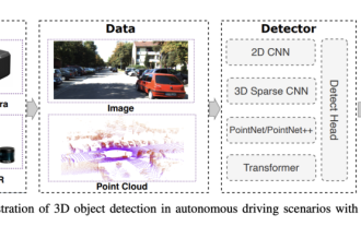
0.Written in front&& Personal understanding that autonomous driving systems rely on advanced perception, decision-making and control technologies, by using various sensors (such as cameras, lidar, radar, etc.) to perceive the surrounding environment, and using algorithms and models for real-time analysis and decision-making. This enables vehicles to recognize road signs, detect and track other vehicles, predict pedestrian behavior, etc., thereby safely operating and adapting to complex traffic environments. This technology is currently attracting widespread attention and is considered an important development area in the future of transportation. one. But what makes autonomous driving difficult is figuring out how to make the car understand what's going on around it. This requires that the three-dimensional object detection algorithm in the autonomous driving system can accurately perceive and describe objects in the surrounding environment, including their locations,
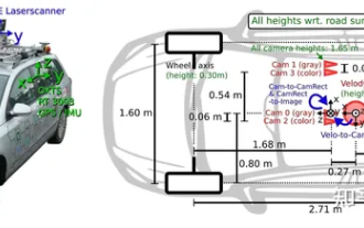 Have you really mastered coordinate system conversion? Multi-sensor issues that are inseparable from autonomous driving
Oct 12, 2023 am 11:21 AM
Have you really mastered coordinate system conversion? Multi-sensor issues that are inseparable from autonomous driving
Oct 12, 2023 am 11:21 AM
The first pilot and key article mainly introduces several commonly used coordinate systems in autonomous driving technology, and how to complete the correlation and conversion between them, and finally build a unified environment model. The focus here is to understand the conversion from vehicle to camera rigid body (external parameters), camera to image conversion (internal parameters), and image to pixel unit conversion. The conversion from 3D to 2D will have corresponding distortion, translation, etc. Key points: The vehicle coordinate system and the camera body coordinate system need to be rewritten: the plane coordinate system and the pixel coordinate system. Difficulty: image distortion must be considered. Both de-distortion and distortion addition are compensated on the image plane. 2. Introduction There are four vision systems in total. Coordinate system: pixel plane coordinate system (u, v), image coordinate system (x, y), camera coordinate system () and world coordinate system (). There is a relationship between each coordinate system,
 This article is enough for you to read about autonomous driving and trajectory prediction!
Feb 28, 2024 pm 07:20 PM
This article is enough for you to read about autonomous driving and trajectory prediction!
Feb 28, 2024 pm 07:20 PM
Trajectory prediction plays an important role in autonomous driving. Autonomous driving trajectory prediction refers to predicting the future driving trajectory of the vehicle by analyzing various data during the vehicle's driving process. As the core module of autonomous driving, the quality of trajectory prediction is crucial to downstream planning control. The trajectory prediction task has a rich technology stack and requires familiarity with autonomous driving dynamic/static perception, high-precision maps, lane lines, neural network architecture (CNN&GNN&Transformer) skills, etc. It is very difficult to get started! Many fans hope to get started with trajectory prediction as soon as possible and avoid pitfalls. Today I will take stock of some common problems and introductory learning methods for trajectory prediction! Introductory related knowledge 1. Are the preview papers in order? A: Look at the survey first, p
 SIMPL: A simple and efficient multi-agent motion prediction benchmark for autonomous driving
Feb 20, 2024 am 11:48 AM
SIMPL: A simple and efficient multi-agent motion prediction benchmark for autonomous driving
Feb 20, 2024 am 11:48 AM
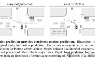
Original title: SIMPL: ASimpleandEfficientMulti-agentMotionPredictionBaselineforAutonomousDriving Paper link: https://arxiv.org/pdf/2402.02519.pdf Code link: https://github.com/HKUST-Aerial-Robotics/SIMPL Author unit: Hong Kong University of Science and Technology DJI Paper idea: This paper proposes a simple and efficient motion prediction baseline (SIMPL) for autonomous vehicles. Compared with traditional agent-cent
 nuScenes' latest SOTA | SparseAD: Sparse query helps efficient end-to-end autonomous driving!
Apr 17, 2024 pm 06:22 PM
nuScenes' latest SOTA | SparseAD: Sparse query helps efficient end-to-end autonomous driving!
Apr 17, 2024 pm 06:22 PM
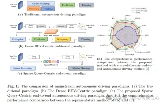
Written in front & starting point The end-to-end paradigm uses a unified framework to achieve multi-tasking in autonomous driving systems. Despite the simplicity and clarity of this paradigm, the performance of end-to-end autonomous driving methods on subtasks still lags far behind single-task methods. At the same time, the dense bird's-eye view (BEV) features widely used in previous end-to-end methods make it difficult to scale to more modalities or tasks. A sparse search-centric end-to-end autonomous driving paradigm (SparseAD) is proposed here, in which sparse search fully represents the entire driving scenario, including space, time, and tasks, without any dense BEV representation. Specifically, a unified sparse architecture is designed for task awareness including detection, tracking, and online mapping. In addition, heavy
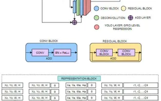 FisheyeDetNet: the first target detection algorithm based on fisheye camera
Apr 26, 2024 am 11:37 AM
FisheyeDetNet: the first target detection algorithm based on fisheye camera
Apr 26, 2024 am 11:37 AM
Target detection is a relatively mature problem in autonomous driving systems, among which pedestrian detection is one of the earliest algorithms to be deployed. Very comprehensive research has been carried out in most papers. However, distance perception using fisheye cameras for surround view is relatively less studied. Due to large radial distortion, standard bounding box representation is difficult to implement in fisheye cameras. To alleviate the above description, we explore extended bounding box, ellipse, and general polygon designs into polar/angular representations and define an instance segmentation mIOU metric to analyze these representations. The proposed model fisheyeDetNet with polygonal shape outperforms other models and simultaneously achieves 49.5% mAP on the Valeo fisheye camera dataset for autonomous driving
