
 Technology peripherals
AI
Perception network for depth, attitude and road estimation in joint driving scenarios
Technology peripherals
AI
Perception network for depth, attitude and road estimation in joint driving scenarios
Perception network for depth, attitude and road estimation in joint driving scenarios

The arXiv paper "JPerceiver: Joint Perception Network for Depth, Pose and Layout Estimation in Driving Scenes", uploaded in July 22, reports on the work of Professor Tao Dacheng of the University of Sydney, Australia, and Beijing JD Research Institute.
Depth estimation, visual odometry (VO) and bird's eye view (BEV) scene layout estimation are three key tasks for driving scene perception, which is the key to motion in autonomous driving. Fundamentals of planning and navigation. Although complementary, they usually focus on separate tasks and rarely address all three simultaneously.
A simple approach is to do it independently in a sequential or parallel manner, but there are three disadvantages, namely 1) depth and VO results are affected by the inherent scale ambiguity problem; 2) BEV layout is usually done independently Estimating roads and vehicles while ignoring explicit overlay-underlay relationships; 3) Although depth maps are useful geometric cues for inferring scene layout, BEV layout is actually predicted directly from front view images without using any depth-related information.
This paper proposes a joint perception framework JPerceiver to solve these problems and simultaneously estimate scale-perceived depth, VO and BEV layout from monocular video sequences. Use a cross-view geometric transformation (CGT) to propagate absolute scale from the road layout to depth and VO according to a carefully designed scale loss. At the same time, a cross-view and cross-modal transfer (CCT) module is designed to use depth clues to reason about road and vehicle layout through attention mechanisms. JPerceiver is trained in an end-to-end multi-task learning method, in which the CGT scale loss and CCT modules promote knowledge transfer between tasks and facilitate feature learning for each task.
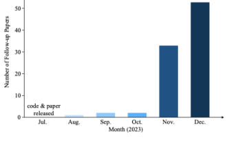
Code and model can be downloaded
https://github.com/sunnyHelen/JPerceiver. As shown in the figure, JPerceiver consists of three networks: depth, attitude and road layout, all based on the encoder-decoder architecture. The depth network aims to predict the depth map Dt of the current frame It, where each depth value represents the distance between a 3D point and the camera. The goal of the pose network is to predict the pose transformation Tt → t m between the current frame It and its adjacent frame It m. The goal of the road layout network is to estimate the BEV layout Lt of the current frame, that is, the semantic occupancy of roads and vehicles in the top-view Cartesian plane. The three networks are jointly optimized during training.
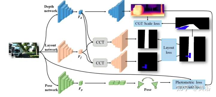 #The two networks predicting depth and pose are jointly optimized with photometric loss and smoothness loss in a self-supervised manner. In addition, the CGT scale loss is also designed to solve the scale ambiguity problem of monocular depth and VO estimation.
In order to achieve scale-aware environment perception, using the scale information in the BEV layout, the scale loss of CGT is proposed for depth estimation and VO. Since the BEV layout shows the semantic occupancy in the BEV Cartesian plane, it covers the range of Z meters in front of the vehicle and (Z/2) meters to the left and right respectively. It provides a natural distance field z, the metric distance zij of each pixel relative to the own vehicle, as shown in the figure:
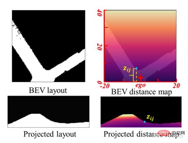 Assume that the BEV plane is the ground , its origin is just below the origin of the self-vehicle coordinate system. Based on the camera external parameters, the BEV plane can be projected to the forward camera through homography transformation. Therefore, the BEV distance field z can be projected into the forward camera, as shown in the figure above, and used to adjust the predicted depth d, thus deriving the CGT scale loss:
 For roads For layout estimation, an encoder-decoder network structure is adopted. It is worth noting that a shared encoder is used as a feature extractor and different decoders to learn the BEV layout of different semantic categories simultaneously. In addition, a CCT module is designed to enhance feature interaction and knowledge transfer between tasks, and provide 3-D geometric information for BEV’s spatial reasoning. In order to regularize the road layout network, various loss terms are combined together to form a hybrid loss and achieve different classes of balanced optimization.
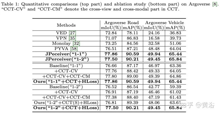
CCT studies the correlation between the forward view feature Ff, BEV layout feature Fb, re-converted forward feature Ff′ and forward depth feature FD, and refines the layout features accordingly, as shown in the figure Shown: divided into two parts, namely
CCT-CVand CCT-CM of the cross-view module and the cross-modal module.
In CCT, Ff and Fd are extracted by the encoder of the corresponding perceptual branch, while Fb is obtained by a view projection MLP to convert Ff to BEV, and a cycle loss constrained same MLP to re-convert it to Ff′.
In CCT-CV, the cross-attention mechanism is used to discover the geometric correspondence between the forward view and BEV features, and then guides the refinement of the forward view information and prepares for BEV inference. In order to make full use of the forward view image features, Fb and Ff are projected to patches: Qbi and Kbi, as query and key respectively.
In addition to utilizing forward view features, CCT-CM is also deployed to impose 3-D geometric information from Fd. Since Fd is extracted from the forward view image, it is reasonable to use Ff as a bridge to reduce the cross-modal gap and learn the correspondence between Fd and Fb. Fd plays the role of Value, thereby obtaining valuable 3-D geometric information related to BEV information and further improving the accuracy of road layout estimation.
In the process of exploring a joint learning framework to simultaneously predict different layouts, there are large differences in the characteristics and distribution of different semantic categories. For features, the road layout in driving scenarios usually needs to be connected, while different vehicle targets must be segmented.
Regarding the distribution, more straight road scenes are observed than turning scenes, which is reasonable in real data sets. This difference and imbalance increase the difficulty of BEV layout learning, especially jointly predicting different categories, since simple cross-entropy (CE) loss or L1 loss fails in this case. Several segmentation losses, including distribution-based CE loss, region-based IoU loss, and boundary loss, are combined into a hybrid loss to predict the layout of each category.
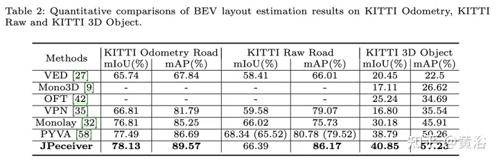
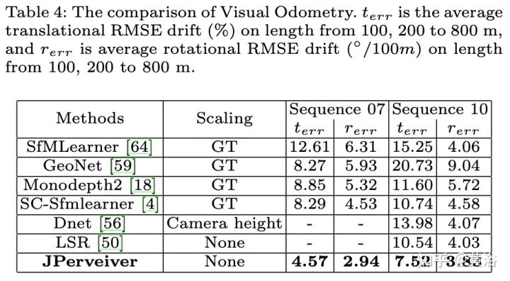
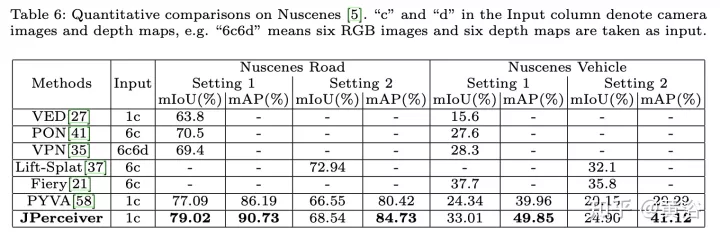
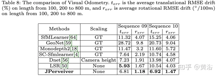
The experimental results are as follows:
 ##
##
The above is the detailed content of Perception network for depth, attitude and road estimation in joint driving scenarios. For more information, please follow other related articles on the PHP Chinese website!

Hot AI Tools

Undresser.AI Undress
AI-powered app for creating realistic nude photos

AI Clothes Remover
Online AI tool for removing clothes from photos.

Undress AI Tool
Undress images for free

Clothoff.io
AI clothes remover

AI Hentai Generator
Generate AI Hentai for free.

Hot Article
Hot Tools

Notepad++7.3.1
Easy-to-use and free code editor

SublimeText3 Chinese version
Chinese version, very easy to use

Zend Studio 13.0.1
Powerful PHP integrated development environment

Dreamweaver CS6
Visual web development tools

SublimeText3 Mac version
God-level code editing software (SublimeText3)
Hot Topics
 1386
1386
 52
52

 Why is Gaussian Splatting so popular in autonomous driving that NeRF is starting to be abandoned?
Jan 17, 2024 pm 02:57 PM
Why is Gaussian Splatting so popular in autonomous driving that NeRF is starting to be abandoned?
Jan 17, 2024 pm 02:57 PM
Written above & the author’s personal understanding Three-dimensional Gaussiansplatting (3DGS) is a transformative technology that has emerged in the fields of explicit radiation fields and computer graphics in recent years. This innovative method is characterized by the use of millions of 3D Gaussians, which is very different from the neural radiation field (NeRF) method, which mainly uses an implicit coordinate-based model to map spatial coordinates to pixel values. With its explicit scene representation and differentiable rendering algorithms, 3DGS not only guarantees real-time rendering capabilities, but also introduces an unprecedented level of control and scene editing. This positions 3DGS as a potential game-changer for next-generation 3D reconstruction and representation. To this end, we provide a systematic overview of the latest developments and concerns in the field of 3DGS for the first time.
 How to solve the long tail problem in autonomous driving scenarios?
Jun 02, 2024 pm 02:44 PM
How to solve the long tail problem in autonomous driving scenarios?
Jun 02, 2024 pm 02:44 PM
Yesterday during the interview, I was asked whether I had done any long-tail related questions, so I thought I would give a brief summary. The long-tail problem of autonomous driving refers to edge cases in autonomous vehicles, that is, possible scenarios with a low probability of occurrence. The perceived long-tail problem is one of the main reasons currently limiting the operational design domain of single-vehicle intelligent autonomous vehicles. The underlying architecture and most technical issues of autonomous driving have been solved, and the remaining 5% of long-tail problems have gradually become the key to restricting the development of autonomous driving. These problems include a variety of fragmented scenarios, extreme situations, and unpredictable human behavior. The "long tail" of edge scenarios in autonomous driving refers to edge cases in autonomous vehicles (AVs). Edge cases are possible scenarios with a low probability of occurrence. these rare events
 Choose camera or lidar? A recent review on achieving robust 3D object detection
Jan 26, 2024 am 11:18 AM
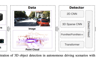
Choose camera or lidar? A recent review on achieving robust 3D object detection
Jan 26, 2024 am 11:18 AM
0.Written in front&& Personal understanding that autonomous driving systems rely on advanced perception, decision-making and control technologies, by using various sensors (such as cameras, lidar, radar, etc.) to perceive the surrounding environment, and using algorithms and models for real-time analysis and decision-making. This enables vehicles to recognize road signs, detect and track other vehicles, predict pedestrian behavior, etc., thereby safely operating and adapting to complex traffic environments. This technology is currently attracting widespread attention and is considered an important development area in the future of transportation. one. But what makes autonomous driving difficult is figuring out how to make the car understand what's going on around it. This requires that the three-dimensional object detection algorithm in the autonomous driving system can accurately perceive and describe objects in the surrounding environment, including their locations,
 Have you really mastered coordinate system conversion? Multi-sensor issues that are inseparable from autonomous driving
Oct 12, 2023 am 11:21 AM
Have you really mastered coordinate system conversion? Multi-sensor issues that are inseparable from autonomous driving
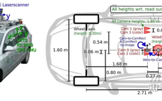
Oct 12, 2023 am 11:21 AM
The first pilot and key article mainly introduces several commonly used coordinate systems in autonomous driving technology, and how to complete the correlation and conversion between them, and finally build a unified environment model. The focus here is to understand the conversion from vehicle to camera rigid body (external parameters), camera to image conversion (internal parameters), and image to pixel unit conversion. The conversion from 3D to 2D will have corresponding distortion, translation, etc. Key points: The vehicle coordinate system and the camera body coordinate system need to be rewritten: the plane coordinate system and the pixel coordinate system. Difficulty: image distortion must be considered. Both de-distortion and distortion addition are compensated on the image plane. 2. Introduction There are four vision systems in total. Coordinate system: pixel plane coordinate system (u, v), image coordinate system (x, y), camera coordinate system () and world coordinate system (). There is a relationship between each coordinate system,
 This article is enough for you to read about autonomous driving and trajectory prediction!
Feb 28, 2024 pm 07:20 PM
This article is enough for you to read about autonomous driving and trajectory prediction!
Feb 28, 2024 pm 07:20 PM
Trajectory prediction plays an important role in autonomous driving. Autonomous driving trajectory prediction refers to predicting the future driving trajectory of the vehicle by analyzing various data during the vehicle's driving process. As the core module of autonomous driving, the quality of trajectory prediction is crucial to downstream planning control. The trajectory prediction task has a rich technology stack and requires familiarity with autonomous driving dynamic/static perception, high-precision maps, lane lines, neural network architecture (CNN&GNN&Transformer) skills, etc. It is very difficult to get started! Many fans hope to get started with trajectory prediction as soon as possible and avoid pitfalls. Today I will take stock of some common problems and introductory learning methods for trajectory prediction! Introductory related knowledge 1. Are the preview papers in order? A: Look at the survey first, p
 SIMPL: A simple and efficient multi-agent motion prediction benchmark for autonomous driving
Feb 20, 2024 am 11:48 AM
SIMPL: A simple and efficient multi-agent motion prediction benchmark for autonomous driving
Feb 20, 2024 am 11:48 AM
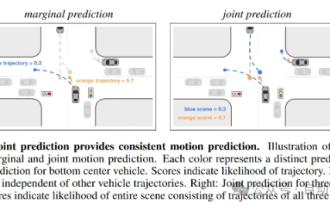
Original title: SIMPL: ASimpleandEfficientMulti-agentMotionPredictionBaselineforAutonomousDriving Paper link: https://arxiv.org/pdf/2402.02519.pdf Code link: https://github.com/HKUST-Aerial-Robotics/SIMPL Author unit: Hong Kong University of Science and Technology DJI Paper idea: This paper proposes a simple and efficient motion prediction baseline (SIMPL) for autonomous vehicles. Compared with traditional agent-cent
 Let's talk about end-to-end and next-generation autonomous driving systems, as well as some misunderstandings about end-to-end autonomous driving?
Apr 15, 2024 pm 04:13 PM
Let's talk about end-to-end and next-generation autonomous driving systems, as well as some misunderstandings about end-to-end autonomous driving?
Apr 15, 2024 pm 04:13 PM
In the past month, due to some well-known reasons, I have had very intensive exchanges with various teachers and classmates in the industry. An inevitable topic in the exchange is naturally end-to-end and the popular Tesla FSDV12. I would like to take this opportunity to sort out some of my thoughts and opinions at this moment for your reference and discussion. How to define an end-to-end autonomous driving system, and what problems should be expected to be solved end-to-end? According to the most traditional definition, an end-to-end system refers to a system that inputs raw information from sensors and directly outputs variables of concern to the task. For example, in image recognition, CNN can be called end-to-end compared to the traditional feature extractor + classifier method. In autonomous driving tasks, input data from various sensors (camera/LiDAR
 nuScenes' latest SOTA | SparseAD: Sparse query helps efficient end-to-end autonomous driving!
Apr 17, 2024 pm 06:22 PM
nuScenes' latest SOTA | SparseAD: Sparse query helps efficient end-to-end autonomous driving!
Apr 17, 2024 pm 06:22 PM
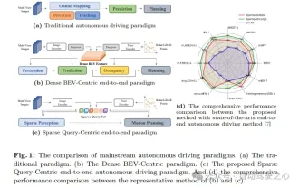
Written in front & starting point The end-to-end paradigm uses a unified framework to achieve multi-tasking in autonomous driving systems. Despite the simplicity and clarity of this paradigm, the performance of end-to-end autonomous driving methods on subtasks still lags far behind single-task methods. At the same time, the dense bird's-eye view (BEV) features widely used in previous end-to-end methods make it difficult to scale to more modalities or tasks. A sparse search-centric end-to-end autonomous driving paradigm (SparseAD) is proposed here, in which sparse search fully represents the entire driving scenario, including space, time, and tasks, without any dense BEV representation. Specifically, a unified sparse architecture is designed for task awareness including detection, tracking, and online mapping. In addition, heavy
