
The core of the unmanned driving system can be summarized into three parts: perception (Perception), planning (Planning) and control (Control). The interaction of these parts and their interaction with vehicle hardware and other vehicles can be used The following figure represents:
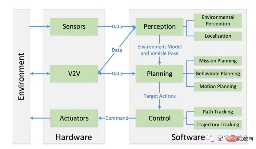
Perception refers to the ability of an unmanned driving system to collect information from the environment and extract relevant knowledge from it . Among them, Environmental Perception specifically refers to the ability to understand the scene of the environment, such as the location of obstacles, detection of road signs/marks, detection of pedestrians and vehicles, and semantic classification of data. Generally speaking, localization is also a part of perception. Localization is the ability of an unmanned vehicle to determine its position relative to the environment.
Planning is the process of autonomous vehicles making some purposeful decisions for a certain goal. For autonomous vehicles, this goal usually refers to arriving at the destination from the starting point. while avoiding obstacles and continuously optimizing driving trajectories and behaviors to ensure the safety and comfort of passengers. The planning layer is usually subdivided into three layers: mission planning, behavioral planning and motion planning.
Finally, control is the ability of the unmanned vehicle to accurately execute planned actions, which originate from higher layers.
In order to ensure that there is no For people and vehicles to understand and grasp the environment, the environmental perception part of the unmanned driving system usually needs to obtain a large amount of information about the surrounding environment, specifically including: the location, speed and possible behaviors of obstacles, drivable areas, traffic rules, etc. wait. Unmanned vehicles usually obtain this information by fusing data from multiple sensors such as Lidar, Camera, and Millimeter Wave Radar. In this section, we briefly take a look at the role of Lidar and cameras in autonomous vehicles. Applications in human and vehicle sensing.
Lidar is a type of device that uses lasers for detection and ranging. It can send millions of light pulses to the environment every second. Its interior is a rotating structure. , which enables lidar to build a 3D map of the surrounding environment in real time.
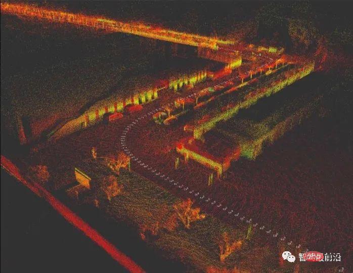
Generally speaking, lidar rotates and scans the surrounding environment at a speed of about 10Hz. The result of one scan is a 3-dimensional map composed of dense points. Each point has ( x, y, z) information, this graph is called a Point Cloud Graph, as shown in the figure below, which is a point cloud map created using Velodyne VLP-32c lidar:
Lidar is still the most important sensor in unmanned driving systems due to its reliability. However, in real-life use, lidar is not perfect. , there is often a problem that the point cloud is too sparse, or even some points are lost. For irregular object surfaces, it is difficult to identify the pattern using lidar. In situations such as heavy rain, lidar cannot be used.
In order to understand point cloud information, generally speaking, we perform two-step operations on point cloud data: segmentation (Segmentation) and classification (Classification). Among them, segmentation is to cluster discrete points in the point cloud image into several wholes, while classification is to distinguish which category these wholes belong to (such as pedestrians, vehicles and obstacles). Segmentation algorithms can be classified into the following categories:
After completing the target segmentation of the point cloud, the segmented targets need to be correctly classified. In this process, classification algorithms in machine learning are generally used, such as Support Vector Machine (SVM) for clustering. In recent years, due to the development of deep learning, the industry has begun to use specially designed convolutional neural networks (Convolutional Neural Network, CNN) to classify three-dimensional point cloud clusters.
However, whether it is the feature extraction method - SVM or the original point cloud - CNN method, due to the low resolution of the lidar point cloud itself, for targets with sparse reflection points ( For example, pedestrians), classification based on point cloud is not reliable, so in practice, we often integrate lidar and camera sensors, use the high resolution of the camera to classify targets, and use the reliability of lidar to detect obstacles and Ranging, integrating the advantages of both to complete environment perception.
In driverless systems, we usually use image vision to complete road detection and target detection on the road. Road detection includes detection of road lines (Lane Detection), drivable area detection (Drivable Area Detection); detection of road signs includes detection of other vehicles (Vehicle Detection), pedestrian detection (Pedestrian Detection), traffic signs and Detection and classification of all traffic participants such as traffic signal detection.
The detection of lane lines involves two aspects: the first is to identify the lane lines. For curved lane lines, the curvature can be calculated. The second is to determine the relative position of the vehicle itself to the lane. Line offset (that is, where the autonomous vehicle is on the lane line). One method is to extract some lane features, including edge features (usually gradients, such as the Sobel operator), lane line color features, etc., use polynomials to fit the pixels we think may be lane lines, and then based on the polynomial and The current position of the camera mounted on the vehicle determines the curvature of the lane ahead and the vehicle's deviation relative to the lane.
One current approach to detecting drivable areas is to use a deep neural network to directly segment the scene, that is, by training a deep neural network that classifies pixels pixel by pixel to complete the detection of drivable areas in the image. Cutting of driving area.
The detection and classification of traffic participants currently mainly rely on deep learning models. Commonly used models include two categories:
At the level of autonomous vehicle perception, The importance of positioning is self-evident. The unmanned vehicle needs to know its exact position relative to the environment. The positioning error here cannot exceed 10cm. Just imagine, if the positioning error of our unmanned vehicle is 30cm, then this It will be a very dangerous autonomous vehicle (both for pedestrians and passengers), because the planning and execution layer of autonomous driving does not know that there is an error of 30 centimeters, and they still make decisions based on the premise of accurate positioning. Decision-making and control, then the decisions made for certain situations are wrong, causing accidents. It can be seen that unmanned vehicles require high-precision positioning.
The most widely used positioning method for unmanned vehicles is undoubtedly the positioning method that integrates Global Positioning System (GPS) and Inertial Navigation System (Inertial Navigation System). Among them, the positioning accuracy of GPS is in the tens Between meters and centimeters, high-precision GPS sensors are relatively expensive. The positioning method integrating GPS/IMU cannot achieve high-precision positioning when the GPS signal is missing or weak, such as in underground parking lots and urban areas surrounded by high-rise buildings. Therefore, it can only be applied to unmanned driving tasks in some scenarios.
Map-assisted positioning algorithm is another widely used unmanned vehicle positioning algorithm. Simultaneous Localization And Mapping (SLAM) is the representative of this type of algorithm. The goal of SLAM is to construct a map and use the map for positioning. SLAM determines the position of the current vehicle and the position of the current observed features by using the observed environmental features.
This is a process that uses past priors and current observations to estimate the current position. In practice, we usually use a Bayesian filter to complete it. Specifically, It includes Kalman Filter, Extended Kalman Filter and Particle Filter.
Although SLAM is a research hotspot in the field of robot positioning, there are problems with using SLAM positioning in the actual development process of unmanned vehicles. Unlike robots, unmanned vehicles move over long distances. Yes, a large open environment. In long-distance movements, as the distance increases, the deviation of SLAM positioning will gradually increase, resulting in positioning failure.
In practice, an effective method for positioning unmanned vehicles is to change the scan matching algorithm in the original SLAM. Specifically, we no longer map while positioning, but It uses sensors such as lidar to construct a point cloud map of the area in advance, and adds part of the "semantics" to the map through programming and manual processing (such as specific markings of lane lines, road networks, the location of traffic lights, traffic rules of the current road section, etc. etc.), this map that contains semantics is the high-precision map (HD Map) of our driverless car.
In actual positioning, we use the current lidar scan and the pre-constructed high-precision map to perform point cloud matching to determine the specific position of our unmanned vehicle in the map. This The class methods are collectively called Scan Matching. The most common scan matching method is the Iterative Closest Point (ICP) method, which completes point cloud registration based on the distance measurement between the current scan and the target scan.
In addition, Normal Distributions Transform (NDT) is also a common method for point cloud registration. It achieves registration based on point cloud feature histograms. Positioning methods based on point cloud registration can also achieve positioning accuracy within 10 centimeters.
Although point cloud registration can give the global positioning of unmanned vehicles relative to the map, this type of method relies too much on pre-constructed high-precision maps, and it still fails in open road sections. It needs to be used with GPS positioning. In road sections with relatively single scenes (such as highways), the cost of using GPS plus point cloud matching is relatively high.
Unmanned driving The hierarchical structure design of the planning system originated from the DAPRA Urban Challenge held in 2007. In the competition, most participating teams divided the planning module of the unmanned vehicle into a three-layer design: task planning, behavior planning and action planning. Among them, task Planning is also often called path planning or route planning, which is responsible for relatively top-level path planning, such as path selection from the starting point to the end point.
We can process our current road system into a directed network graph (Directed Graph Network). This directed network graph can represent the connections between roads and traffic rules. , road width and other information, which is essentially the "semantic" part of the high-precision map mentioned in the previous positioning section. This directed network graph is called a Route Network Graph, as follows Pictured:
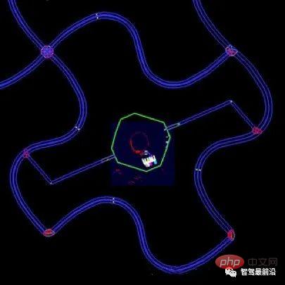
Each directed edge in such a road network graph is weighted. Then, the path planning problem of unmanned vehicles becomes that in the road network graph, in order for the vehicle to reach a certain The goal (usually from point A to point B) is a process of selecting the optimal (i.e., minimum loss) path based on a certain method. Then the problem becomes a directed graph search problem. Traditional algorithms such as Dickos Dijkstra's Algorithm (Dijkstra's Algorithm) and A* Algorithm (A* Algorithm) are mainly used to calculate the optimal path search in discrete graphs, and are used to search for the path with the least loss in the road network graph.
Behavior planning is sometimes also called decision making (Decision Maker). The main task is to follow the goals of task planning and Based on the current local situation (location and behavior of other vehicles and pedestrians, current traffic rules, etc.), make the next decision that the autonomous vehicle should perform. This layer can be understood as the co-pilot of the vehicle. He based on the goal and current situation. The traffic situation instructs the driver whether to follow or overtake, whether to stop and wait for pedestrians to pass or to bypass pedestrians, etc.
One method of behavioral planning is to use a complex finite state machine (FSM) containing a large number of action phrases. The finite state machine starts from a basic state and will Different driving scenarios jump to different action states, and the action phrases are passed to the lower action planning layer. The following figure is a simple finite state machine:
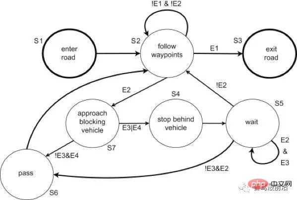
As shown in the figure above, each state is a decision on vehicle action. There are certain jump conditions between states. Some states can self-loop (such as in the figure above tracking state and waiting state). Although it is the mainstream behavioral decision-making method currently used in unmanned vehicles, finite state machines still have great limitations: First, to achieve complex behavioral decisions, a large number of states need to be manually designed; the vehicle may fall into the state of the finite state machine. Considered states; if the finite state machine is not designed with deadlock protection, the vehicle may even fall into some kind of deadlock.
The process of planning a series of actions to achieve a certain purpose (such as avoiding obstacles) is called Action planning. Generally speaking, two indicators are usually used to consider the performance of action planning algorithms: computational efficiency (Computational Efficiency) and completeness (Completeness). The so-called computational efficiency refers to the processing efficiency of completing an action planning. The computational efficiency of action planning algorithms varies greatly. It depends largely on the configuration space. If an action planning algorithm can return a solution in a limited time if there is a solution to the problem, and can return no solution if there is no solution, then we call the action The planning algorithm is complete.
Configuration space: A set that defines all possible configurations of the robot. It defines the dimensions in which the robot can move. For the simplest two-dimensional discrete problem, the configuration space is [x, y], the configuration space of autonomous vehicles can be very complex, depending on the motion planning algorithm used.
After the concept of configuration space is introduced, the action planning of unmanned vehicles becomes: given an initial configuration (Start Configuration), a target configuration (Goal Configuration) ) and several constraints (Constraint), find a series of actions in the configuration space to reach the target configuration. The execution result of these actions is to transfer the unmanned vehicle from the initial configuration to the target configuration while satisfying the constraints.
In the application scenario of unmanned vehicles, the initial configuration is usually the current state of the unmanned vehicle (current position, speed and angular velocity, etc.), and the target configuration is derived from action planning. The upper layer is the behavior planning layer, and the constraints are the movement limits of the vehicle (maximum angle amplitude, maximum acceleration, etc.).
Obviously, the amount of calculation for action planning in a high-dimensional configuration space is very huge. In order to ensure the integrity of the planning algorithm, we have to search almost all possible paths. This This creates the "curse of dimensionality" problem in continuous action planning. The core concept of solving this problem in current action planning is to convert the continuous space model into a discrete model. The specific methods can be summarized into two categories: Combinatorial Planning and Sampling-Based Planning.
Combinatorial methods of motion planning find paths through a continuous configuration space without resorting to approximations. Due to this property, they can be called exact algorithms. Combination methods find a complete solution by building a discrete representation of the planning problem, such as the action planning algorithm used by CMU's self-driving car BOSS in the Darpa Urban Challenge. They first use a path planner to generate alternatives path and target points (these paths and target points are reachable by fusion dynamics), and then select the optimal path through the optimization algorithm.
Another discretization method is Grid Decomposition Approaches. After gridding the configuration space, we can usually use discrete graph search algorithms (such as A* ) to find an optimized path.
Sampling-based methods are widely used due to their probabilistic completeness. The most common algorithms are PRM (Probabilistic Roadmaps), RRT (Rapidly-Exploring Random Tree), FMT (Fast- Marching Trees), in the application of unmanned vehicles, the state sampling method needs to consider the control constraints of the two states, and also needs a method that can effectively query whether the sampling state and the parent state are reachable. Later we will introduce in detail State-Lattice Planners, a sampling-based motion planning algorithm.
The control layer is the lowest layer of the unmanned vehicle system. Its task is to realize the actions we planned, so the control layer The evaluation index of the module is the accuracy of control. There will be measurements inside the control system, and the controller outputs control actions by comparing the vehicle's measurements with our expected state. This process is called feedback control.
Feedback control is widely used in the field of automation control. The most typical feedback controller is the PID controller (Proportional-Integral-Derivative Controller). The control principle of the PID controller It is based on a simple error signal, which consists of three items: error proportion (Proportion), error integral (Integral) and error differential (Derivative).
PID control is still the most widely used controller in the industry because of its simple implementation and stable performance. However, as a pure feedback controller, the PID controller plays an important role in unmanned vehicle control. However, there are certain problems: the PID controller is purely based on the current error feedback. Due to the delay of the braking mechanism, it will bring delay to our control itself. Since there is no internal system model of PID, PID cannot build the delay. In order to solve this problem, we introduce a control method based on model prediction.
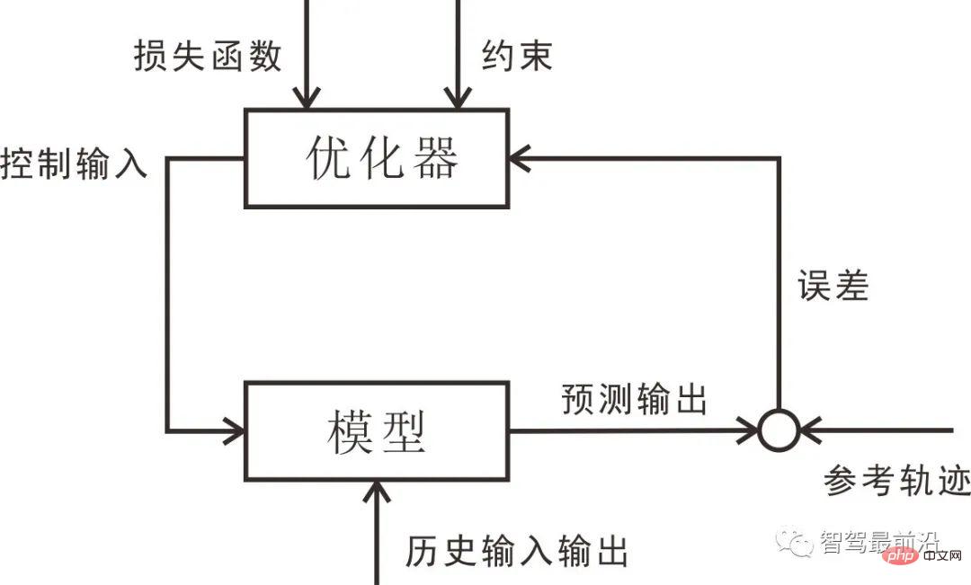
The following figure shows the basic structure of model predictive control. Since model predictive control is optimized based on the motion model, the control delay problem faced in PID control can be considered by establishing a new model. In, so model predictive control has high application value in unmanned vehicle control.
In this summary we have provided an overview of autonomous driving The basic structure of the system, autonomous driving software systems are usually divided into three layers: perception, planning and control. To a certain extent, an unmanned vehicle can be regarded as a "manned robot" under this layered system. Among them, perception specifically includes environmental perception and positioning. In recent years, breakthroughs in deep learning have enabled image-based Perception technology and deep learning are playing an increasingly important role in environmental perception. With the help of artificial intelligence, we are no longer limited to perceiving obstacles, but gradually become understanding what obstacles are, understanding scenes, and even predicting target obstacles. We will learn more about the behavior of objects, machine learning and deep learning in the next two chapters.
In actual unmanned vehicle perception, we usually need to fuse multiple measurements such as lidar, camera and millimeter wave radar. What is involved here is Kalman filtering, extended Kalman Fusion algorithms such as filtering and lidar.
There are many positioning methods for unmanned vehicles and robots. The current mainstream method is to use the GPS inertial navigation system fusion method, and the second is to use Lidar point cloud scanning and matching methods. We will focus on ICP, NDT and other based on Point cloud matching algorithm.
The planning module is also divided into three layers: task planning (also called path planning), behavior planning and action planning. The road network and discrete path search algorithms will be introduced later. Task planning method. In behavioral planning, we will focus on the application of finite state machines in behavioral decision-making. At the action planning algorithm layer, we will focus on sampling-based planning methods.
We often use control methods based on model prediction for the control module of unmanned vehicles, but before understanding the model predictive control algorithm, as an understanding of basic feedback control, we have learned about it before PID controller. Next we study the two simplest types of vehicle models - kinematic bicycle models and dynamic bicycle models, and finally, we introduce model predictive control.
Although it is the current consensus in the industry to understand unmanned vehicles as robots and use the thinking developed by robots to process unmanned vehicle systems, there are also some that simply use artificial intelligence or intelligent agents. To complete the case of driverless driving. Among them, end-to-end driverless driving based on deep learning and driving agents based on reinforcement learning are current research hotspots.
The above is the detailed content of Overview of autonomous driving technology framework. For more information, please follow other related articles on the PHP Chinese website!


