 Technology peripherals
 AI
AI
 Understand the application design scheme of autonomous driving radar sensors in one article
Understand the application design scheme of autonomous driving radar sensors in one article
Sensors are key components of driverless cars. The ability to monitor the distance to vehicles ahead, behind or to the side provides vital data to the central controller. Optical and infrared cameras, lasers, ultrasound and radar can all be used to provide data about the surrounding environment, roadways and other vehicles. For example, cameras can be used to detect markings on the road to keep vehicles in the correct lane. This is already used to provide lane departure warning in driver assistance systems (ADAS). Today's ADAS systems also use radar for collision detection warnings and adaptive cruise control, where the vehicle can follow the vehicle in front.
Without driver input, self-driving cars require more sensor systems, often using multiple inputs from different sensors to provide a higher level of assurance. These sensor systems are adapting from proven ADAS implementations, although system architecture is changing to manage a wider range of sensors and higher data rates.
Radar Usage
With the increasing adoption of ADAS systems for adaptive cruise control and collision detection, 24 GHz The cost of radar sensors is falling. These are now becoming requirements for car manufacturers to achieve Europe's five-star NCAP safety rating.
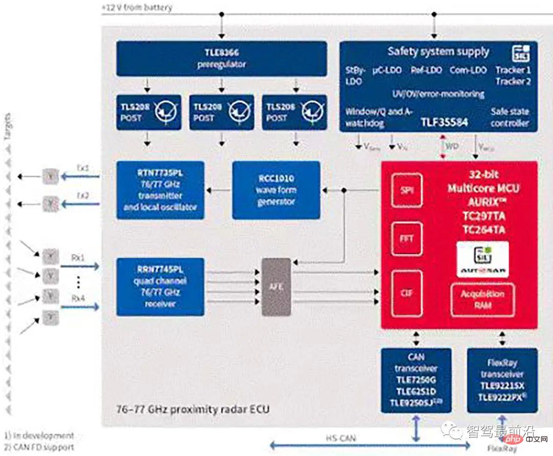
For example, Infineon Technologies’ BGT24M 24GHz radar sensor can be used with an external microcontroller in an electronic control unit (ECU) to modify the throttle to maintain contact with the vehicle ahead. constant distance, ranging up to 20 m, as shown in Figure 1.

Figure 1: Infineon Technologies’ automotive radar sensing system.
Many automotive radar systems use the pulse Doppler method, in which the transmitter operates for a short period of time, called the Pulse Repetition Interval (PRI), and then the system switches to receive mode until The next one fires a pulse. When the radar returns, the reflections are coherently processed to extract the range and relative motion of the detected objects.
Another method is to use continuous wave frequency modulation (CWFM). This uses a continuous carrier frequency that changes over time and the receiver is constantly turned on. To prevent the transmit signal from leaking into the receiver, separate transmit and receive antennas must be used.
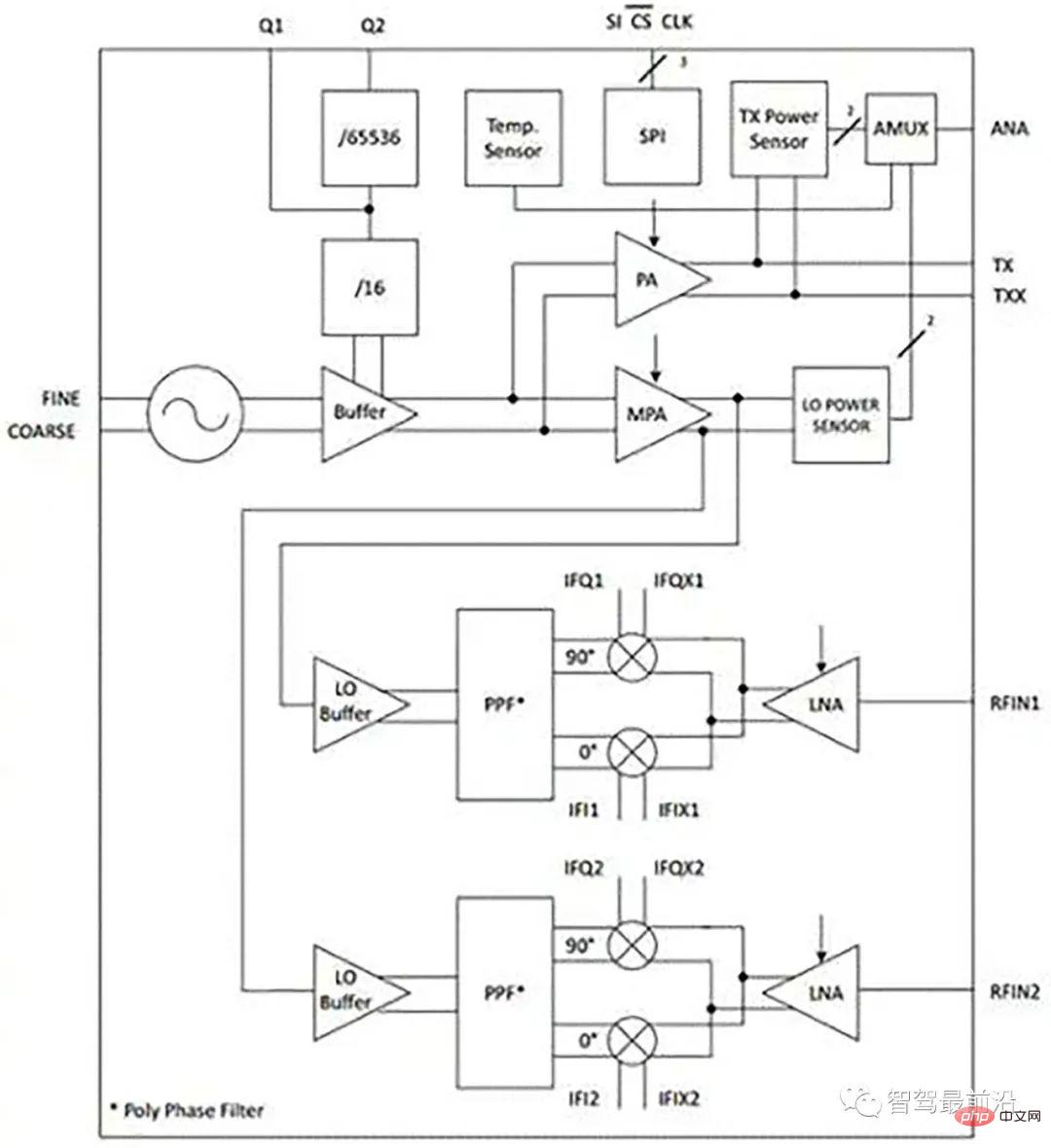
The BGT24MTR12 is a silicon germanium (SiGe) sensor for signal generation and reception operating from 24.0 to 24.25 GHz. It uses a 24 GHz fundamental voltage controlled oscillator and includes a switchable frequency prescaler with output frequencies of 1.5 GHz and 23 kHz.
An RC polyphase filter (PPF) is used for LO quadrature phase generation of the downconverting mixer, while output power sensors and temperature sensors are integrated into the device for monitoring .

Figure 2: Infineon Technologies’ BGT24MTR12 radar sensor.
The device is controlled via SPI, fabricated on 0.18 µm SiGe:C technology, has a cutoff frequency of 200 GHz, and is available in a 32-pin leadless VQFN package.
However, the architecture of autonomous vehicles is changing. Rather than being local to the ECU, data from various radar systems around the vehicle is fed to a central high-performance controller that combines the signals with signals from cameras and possibly lidar laser sensors.
The controller can be a high-performance general-purpose processor with a graphics control unit (GCU), or a field-programmable gate array where signal processing can be handled by dedicated hardware. This places greater emphasis on analog front-end (AFE) interface devices that must handle higher data rates and more data sources.
The types of radar sensors being used are also changing. 77 GHz sensor provides longer range and higher resolution. The 77 GHz or 79 GHz radar sensor can be adjusted in real time to provide long-range sensing up to 200 m within a 10° arc, for example to detect other vehicles, but it can also be used for wider 30° sensing up to 30 m Lower range arc. Higher frequencies provide greater resolution, allowing radar sensor systems to distinguish between multiple objects in real time, such as detecting many pedestrians within a 30° arc, giving controllers of autonomous vehicles more time and more data.
The 77 GHz sensor uses a silicon germanium bipolar transistor with an oscillation frequency of 300 GHz. This allows one radar sensor to be used in a variety of safety systems such as forward alert, collision warning and automatic braking, and the 77 GHz technology is also more resistant to vehicle vibrations, so less filtering is required.

Figure 3: Different use cases for radar sensors in autonomous vehicles provided by NXP.
# The sensor is used to detect the distance, speed and azimuth of the target vehicle in the vehicle coordinate system (VCS). The accuracy of the data depends on the alignment of the radar sensor.
The radar sensor alignment algorithm is performed while the vehicle is operating at frequencies above 40 Hz. It must calculate the misalignment angle within 1 millisecond based on data provided by the radar sensor as well as vehicle speed, the sensor's position on the vehicle and its pointing angle.
Software tools can be used to analyze recorded sensor data captured from road testing of real vehicles. This test data can be used to develop a radar sensor alignment algorithm that uses a squares algorithm to calculate sensor misalignment angles based on raw radar detections and host vehicle speed. This also estimates the accuracy of the calculated angle based on the residual of the square solution.
02 System Architecture
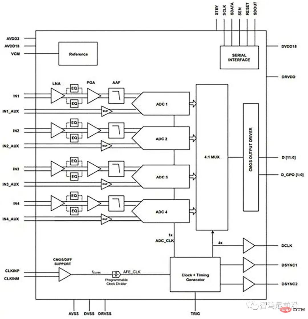
Analog front ends such as Texas Instruments’ AFE5401-Q1 (Figure 4) can be used to connect radar sensors to The rest of the automotive system is shown in Figure 1. The AFE5401 contains four channels, each containing a low-noise amplifier (LNA), selectable equalizer (EQ), programmable gain amplifier (PGA) and anti-aliasing filter, followed by a high-speed 12-bit analog-to-digital signal of 25 MSPS converter (ADC) per channel. The four ADC outputs are multiplexed on a 12-bit, parallel, CMOS-compatible output bus.

Figure 4: Four channels in Texas Instruments’ AFE5401 radar analog front end can be used with multiple sensors.
For low-cost systems, Analog Devices’ AD8284 provides an analog front end with a four-channel differential multiplexer (mux) that can be used with a programmable gain amplifier Single-channel low-noise preamplifier (LNA) powered by (PGA) and anti-aliasing filter (AAF). This also uses a single direct-to-ADC channel, all integrated with a single 12-bit analog-to-digital converter (ADC). The AD8284 also contains a saturation detection circuit to detect high frequency overvoltage conditions that would otherwise be filtered by the AAF. The analog channel gain range is 17 dB to 35 dB in 6 dB increments, and the ADC conversion rate is up to 60 MSPS. The combined input reference voltage noise for the entire channel is 3.5 nV/√Hz at gain.
The output of the AFE is fed to a processor or FPGA such as Microsemi's IGLOO2 or Fusion or Intel's Cyclone IV. This enables the 2D FFT to be implemented in hardware using FPGA design tools to process the FFT and provide the required data about the surrounding objects. This can then be fed into a central controller.
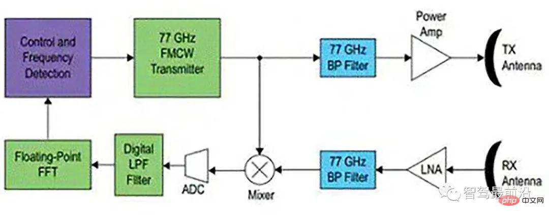
A key challenge for FPGAs is detecting multiple objects, which is more complex for CWFM architectures than pulse Doppler. One approach is to vary the duration and frequency of the ramp and evaluate how the detected frequencies move through the spectrum with different frequency ramp steepness. Since the ramp can change in 1 ms intervals, hundreds of changes can be analyzed per second.

Figure 5: CWFM radar front end used with Intel’s FPGA.
Fusion of data from other sensors can also help, as camera data can be used to distinguish stronger echoes from vehicles from weaker echoes from people, as well as expected Doppler shift type.
Another option is multi-mode radar, which uses CWFM to find targets at longer distances on the highway, and short-range pulse Doppler radar for easier detection of pedestrians of urban areas.
03 Conclusion
Developments in ADAS sensor systems for autonomous vehicles are changing the way radar systems are implemented. Moving from simpler collision avoidance or adaptive cruise control to all-round detection is a significant challenge. Radar is a very popular sensing technology that is widely accepted among car manufacturers and is therefore the technology for this approach. Combining higher frequency 77 GHz sensors with multimode CWFM and pulse Doppler architectures and data from other sensors such as cameras also poses significant challenges to the processing subsystems. Addressing these challenges in a safe, consistent and cost-effective manner is critical to the continued development of autonomous vehicles.
The above is the detailed content of Understand the application design scheme of autonomous driving radar sensors in one article. For more information, please follow other related articles on the PHP Chinese website!

Hot AI Tools

Undresser.AI Undress
AI-powered app for creating realistic nude photos

AI Clothes Remover
Online AI tool for removing clothes from photos.

Undress AI Tool
Undress images for free

Clothoff.io
AI clothes remover

AI Hentai Generator
Generate AI Hentai for free.

Hot Article

Hot Tools

Notepad++7.3.1
Easy-to-use and free code editor

SublimeText3 Chinese version
Chinese version, very easy to use

Zend Studio 13.0.1
Powerful PHP integrated development environment

Dreamweaver CS6
Visual web development tools

SublimeText3 Mac version
God-level code editing software (SublimeText3)

Hot Topics
 1378
1378
 52
52
 Why is Gaussian Splatting so popular in autonomous driving that NeRF is starting to be abandoned?
Jan 17, 2024 pm 02:57 PM
Written above & the author’s personal understanding Three-dimensional Gaussiansplatting (3DGS) is a transformative technology that has emerged in the fields of explicit radiation fields and computer graphics in recent years. This innovative method is characterized by the use of millions of 3D Gaussians, which is very different from the neural radiation field (NeRF) method, which mainly uses an implicit coordinate-based model to map spatial coordinates to pixel values. With its explicit scene representation and differentiable rendering algorithms, 3DGS not only guarantees real-time rendering capabilities, but also introduces an unprecedented level of control and scene editing. This positions 3DGS as a potential game-changer for next-generation 3D reconstruction and representation. To this end, we provide a systematic overview of the latest developments and concerns in the field of 3DGS for the first time.
 How to solve the long tail problem in autonomous driving scenarios?
Jun 02, 2024 pm 02:44 PM
Yesterday during the interview, I was asked whether I had done any long-tail related questions, so I thought I would give a brief summary. The long-tail problem of autonomous driving refers to edge cases in autonomous vehicles, that is, possible scenarios with a low probability of occurrence. The perceived long-tail problem is one of the main reasons currently limiting the operational design domain of single-vehicle intelligent autonomous vehicles. The underlying architecture and most technical issues of autonomous driving have been solved, and the remaining 5% of long-tail problems have gradually become the key to restricting the development of autonomous driving. These problems include a variety of fragmented scenarios, extreme situations, and unpredictable human behavior. The "long tail" of edge scenarios in autonomous driving refers to edge cases in autonomous vehicles (AVs). Edge cases are possible scenarios with a low probability of occurrence. these rare events
 Choose camera or lidar? A recent review on achieving robust 3D object detection
Jan 26, 2024 am 11:18 AM
0.Written in front&& Personal understanding that autonomous driving systems rely on advanced perception, decision-making and control technologies, by using various sensors (such as cameras, lidar, radar, etc.) to perceive the surrounding environment, and using algorithms and models for real-time analysis and decision-making. This enables vehicles to recognize road signs, detect and track other vehicles, predict pedestrian behavior, etc., thereby safely operating and adapting to complex traffic environments. This technology is currently attracting widespread attention and is considered an important development area in the future of transportation. one. But what makes autonomous driving difficult is figuring out how to make the car understand what's going on around it. This requires that the three-dimensional object detection algorithm in the autonomous driving system can accurately perceive and describe objects in the surrounding environment, including their locations,
 Have you really mastered coordinate system conversion? Multi-sensor issues that are inseparable from autonomous driving
Oct 12, 2023 am 11:21 AM
The first pilot and key article mainly introduces several commonly used coordinate systems in autonomous driving technology, and how to complete the correlation and conversion between them, and finally build a unified environment model. The focus here is to understand the conversion from vehicle to camera rigid body (external parameters), camera to image conversion (internal parameters), and image to pixel unit conversion. The conversion from 3D to 2D will have corresponding distortion, translation, etc. Key points: The vehicle coordinate system and the camera body coordinate system need to be rewritten: the plane coordinate system and the pixel coordinate system. Difficulty: image distortion must be considered. Both de-distortion and distortion addition are compensated on the image plane. 2. Introduction There are four vision systems in total. Coordinate system: pixel plane coordinate system (u, v), image coordinate system (x, y), camera coordinate system () and world coordinate system (). There is a relationship between each coordinate system,
 This article is enough for you to read about autonomous driving and trajectory prediction!
Feb 28, 2024 pm 07:20 PM
Trajectory prediction plays an important role in autonomous driving. Autonomous driving trajectory prediction refers to predicting the future driving trajectory of the vehicle by analyzing various data during the vehicle's driving process. As the core module of autonomous driving, the quality of trajectory prediction is crucial to downstream planning control. The trajectory prediction task has a rich technology stack and requires familiarity with autonomous driving dynamic/static perception, high-precision maps, lane lines, neural network architecture (CNN&GNN&Transformer) skills, etc. It is very difficult to get started! Many fans hope to get started with trajectory prediction as soon as possible and avoid pitfalls. Today I will take stock of some common problems and introductory learning methods for trajectory prediction! Introductory related knowledge 1. Are the preview papers in order? A: Look at the survey first, p
 SIMPL: A simple and efficient multi-agent motion prediction benchmark for autonomous driving
Feb 20, 2024 am 11:48 AM
Original title: SIMPL: ASimpleandEfficientMulti-agentMotionPredictionBaselineforAutonomousDriving Paper link: https://arxiv.org/pdf/2402.02519.pdf Code link: https://github.com/HKUST-Aerial-Robotics/SIMPL Author unit: Hong Kong University of Science and Technology DJI Paper idea: This paper proposes a simple and efficient motion prediction baseline (SIMPL) for autonomous vehicles. Compared with traditional agent-cent
 nuScenes' latest SOTA | SparseAD: Sparse query helps efficient end-to-end autonomous driving!
Apr 17, 2024 pm 06:22 PM
Written in front & starting point The end-to-end paradigm uses a unified framework to achieve multi-tasking in autonomous driving systems. Despite the simplicity and clarity of this paradigm, the performance of end-to-end autonomous driving methods on subtasks still lags far behind single-task methods. At the same time, the dense bird's-eye view (BEV) features widely used in previous end-to-end methods make it difficult to scale to more modalities or tasks. A sparse search-centric end-to-end autonomous driving paradigm (SparseAD) is proposed here, in which sparse search fully represents the entire driving scenario, including space, time, and tasks, without any dense BEV representation. Specifically, a unified sparse architecture is designed for task awareness including detection, tracking, and online mapping. In addition, heavy
 FisheyeDetNet: the first target detection algorithm based on fisheye camera
Apr 26, 2024 am 11:37 AM
Target detection is a relatively mature problem in autonomous driving systems, among which pedestrian detection is one of the earliest algorithms to be deployed. Very comprehensive research has been carried out in most papers. However, distance perception using fisheye cameras for surround view is relatively less studied. Due to large radial distortion, standard bounding box representation is difficult to implement in fisheye cameras. To alleviate the above description, we explore extended bounding box, ellipse, and general polygon designs into polar/angular representations and define an instance segmentation mIOU metric to analyze these representations. The proposed model fisheyeDetNet with polygonal shape outperforms other models and simultaneously achieves 49.5% mAP on the Valeo fisheye camera dataset for autonomous driving


