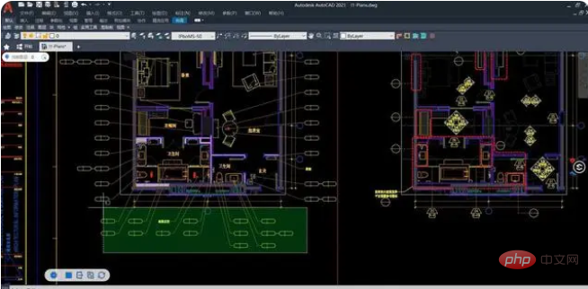
What is the difference between cad and cdr
The difference between cad and cdr is: 1. cad is computer-aided design, which uses computers and graphics equipment to help designers carry out design work, while cdr is vector graphics software, mainly used to make some logos or Vector pictures; 2. CAD is mainly used in architectural design, mechanical design, clothing design and other fields, while CDR focuses on graphic design, focusing on graphics and typesetting.

The operating system of this tutorial: Windows 11 system, cad2023 version, Dell G3 computer.
Speaking of software CAD and CDR, I believe everyone is familiar with it. These two softwares are commonly seen drawing software and have been widely used in the field of design and drawing. So, what is the difference between CAD and CDR? Let us analyze it together!
The difference between CAD and CDR
CAD is mainly used for drawing in construction and mechanical manufacturing, and is very convenient for making mechanical graphics; CDR is mainly used for the design of flat images , such as advertising planning, graphic design, etc. Both are vector graphics design software, and CAD cannot do typesetting.

Application fields of CAD software
Engineering drawing: construction engineering, decoration design, environmental art design, hydropower engineering, civil construction etc.; Industrial drawing: precision parts, molds, equipment, etc.; Garment processing: mainly used for garment pattern making. CAD software is widely used in civil construction, decoration, urban planning, garden design, electronic circuits, mechanical design, clothing, shoes and hats, aerospace, light industry, chemical industry and many other fields.

CDR software application field
CDR is mainly used for typesetting, CorelDRAW is vector graphics software, mainly used to create some For logos or vector pictures, it can also be used to make business cards, leaflets, and books. Generally, it deals with vector pictures. It can also make line drawings for logos, advertisements, illustrations, etc.

The above is the detailed content of What is the difference between cad and cdr. For more information, please follow other related articles on the PHP Chinese website!

Hot AI Tools

Undresser.AI Undress
AI-powered app for creating realistic nude photos

AI Clothes Remover
Online AI tool for removing clothes from photos.

Undress AI Tool
Undress images for free

Clothoff.io
AI clothes remover

AI Hentai Generator
Generate AI Hentai for free.

Hot Article

Hot Tools

Notepad++7.3.1
Easy-to-use and free code editor

SublimeText3 Chinese version
Chinese version, very easy to use

Zend Studio 13.0.1
Powerful PHP integrated development environment

Dreamweaver CS6
Visual web development tools

SublimeText3 Mac version
God-level code editing software (SublimeText3)

Hot Topics
 Why is the CAD layer unlocked but cannot be selected?
Sep 12, 2023 pm 03:41 PM
The cad layer is not locked but the objects in it cannot be selected, which may be caused by the visibility, property settings, order or software problems of the layer. Detailed introduction: 1. Layer visibility, make sure the layer's visibility is set to "visible"; 2. Property settings, check the layer's property settings and make sure they match the current drawing environment; 3. Sequence , adjust the order of layers to ensure that the object to be selected is above other objects; 4. Software problems, restart the CAD software, or update to the latest version.
 Why can't CAD be copied to the clipboard?
Sep 11, 2023 pm 03:32 PM
Reasons why CAD cannot be copied to the clipboard may be software issues, permission restrictions, graphics complexity, clipboard issues, and improper user operation. Detailed introduction: 1. Software problems, restart the CAD software, or upgrade to the latest version; 2. Permission restrictions, you can contact the system administrator or network administrator to obtain higher permissions; 3. Graphics complexity, try to simplify the graphics , delete unnecessary objects or layers, or split the graphics into multiple smaller parts for copying; 4. Clipboard problem, try clearing the clipboard, etc.
 How to solve the problem that the top functional area of cad is missing
Dec 08, 2023 pm 05:15 PM
Solutions to the disappearance of the top functional area of CAD: 1. Shortcut key operation; 2. Menu bar operation; 3. Right-click menu operation; 4. Reset the CAD interface; 5. Adjust the display mode of the functional area; 6. Adjust the CAD interface Layout; 7. Use shortcut key combinations; 8. Customize shortcut keys; 9. Update or reinstall CAD software. Detailed introduction: 1. Shortcut key operation. In the CAD interface, if the functional area disappears, you can redisplay it by using the shortcut key; 2. Menu bar operation. In the CAD interface, open the menu bar and find the "Tools" option, etc. wait.
 How to convert AI files to CDR format
Feb 19, 2024 pm 04:09 PM
AI files refer to vector graphics files created by Adobe Illustrator (AI for short) software, while CDR files refer to vector graphics files created by CorelDRAW software. Since these two softwares are developed by different manufacturers, their file formats are different and cannot be directly converted to each other. However, we can convert AI files to CDR files through some methods. A commonly used conversion method will be introduced below. Step 1: Export AI files to EPS format AdobeIllust
 cad break line command
Aug 08, 2023 am 11:46 AM
The CAD break line command refers to a command used in computer-aided design software to break line segments or polylines. This command is very commonly used in CAD software because line segments often need to be modified and adjusted during the design process. Use break lines. Commands make it easy to split a line segment into multiple segments to meet design needs.
 How to draw three-dimensional graphics in CAD
Feb 27, 2024 pm 07:00 PM
In CAD software, the three-dimensional drawing function allows designers to express design concepts more intuitively and create three-dimensional graphics. However, many users may not yet understand how to use CAD to draw three-dimensional graphics, so this article will introduce you in detail how to use CAD software to draw three-dimensional graphics to help you master this key skill. If you want to know more, please continue reading this article. I believe this tutorial guide will be helpful to you. Steps for drawing three-dimensional graphics in CAD: 1. Open the CAD2023 software and create a blank document. Create an 8-sided shape. As shown below: 2. Click the area tool in the drawing. Or enter a space after entering the REGION command. As shown below: 3. Select the object in REGION.
 What to do if the middle mouse button cannot pan in win7cad
Jul 12, 2023 pm 10:37 PM
Solution to the problem that the middle mouse button cannot pan in win7cad. When many friends use the win7 system, they usually need to use the middle mouse button when drawing with autoCAD. Recently, some friends encountered the problem that the middle mouse button cannot translate when using CAD. what should we do? Let us share the solution. 1. Enter the OP command directly in the command line, find and select the options window. 2. Or find and open the Options window in the Tools menu. 3. Click Reset under the options window to restore the default settings. 4. In fact, the middle mouse button has a system variable to set mbuttonpan. Setting the system variable to 1 can restore it, which is much more convenient than editing the visuallisp program. 5. Of course, the translation work of the middle button
 How to merge a graphic after CAD rectangles are scattered
Feb 28, 2024 pm 12:10 PM
When using CAD software, we often encounter situations where we need to recombine "scattered" rectangular objects into a single graphic. This need arises in many fields, such as space planning, mechanical design and architectural drawings. In order to meet this demand, we need to understand and master some key functions in CAD software. Next, the editor of this website will introduce you in detail how to complete this task in the CAD environment. Users who have doubts can come and follow this article to learn. Method for merging CAD rectangles into one graphic after breaking them up: 1. Open the CAD2023 software, create a rectangle, and then enter the X command and a space. As shown below: 2. Select the rectangular object and space it. You can break up the objects. 3. Select all open lines


