Smart car functional safety software architecture
01 E-GAS Safety Architecture Thought
Automobile functional safety aims to control the risk of personal harm caused by the failure of electronic and electrical systems within a reasonable range. The following figure is a common electronic and electrical system hardware composition diagram. The components of an electronic and electrical system, in addition to the visible hardware in the figure, also include software that is not visible in the figure.
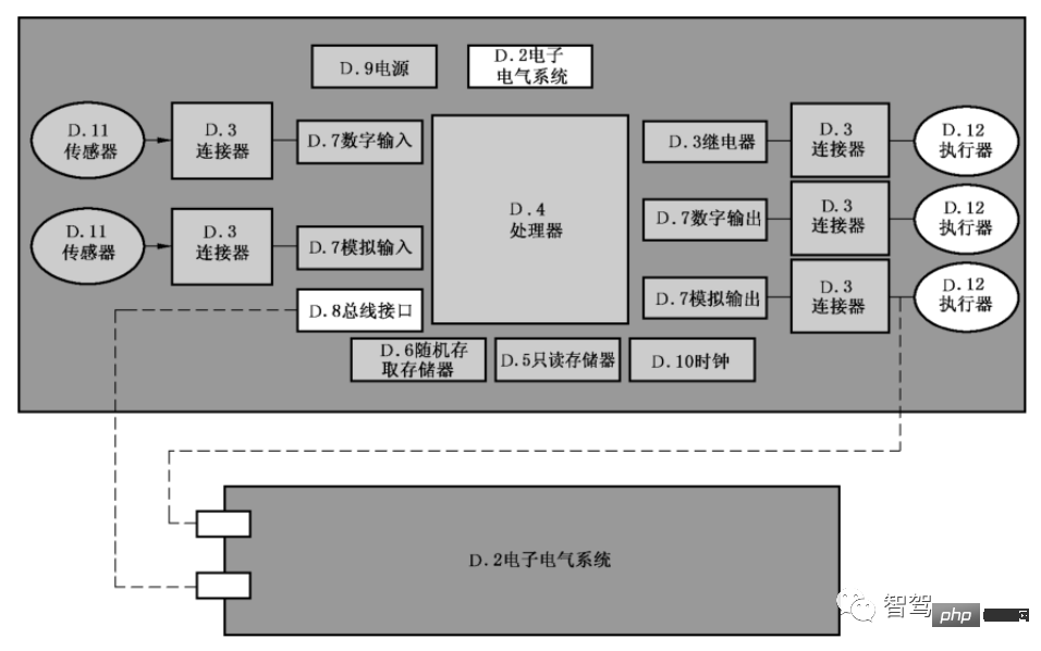
##Figure 1 Commonly used electronic and electrical hardware systems
The failure of electronic and electrical systems includes both systemic failures caused by software and hardware design errors and failures caused by random hardware failures. According to the system architecture, various safety mechanisms need to be designed to prevent and detect functional failures, and to avoid or reduce the harm when a failure occurs. This requires a strong functional safety software architecture to manage and control these safety mechanisms and reduce the overall development difficulty of functional safety.
Currently, E-GAS (Standardized E-Gas Monitoring Concept for Gasoline and Diesel Engine Control Units) is undoubtedly the most widely used security software architecture solution. Although E-GAS was originally proposed as a safety architecture solution for gasoline/diesel engine management systems, after simple adaptation, it can also be used in body systems, transmission systems, and new energy three-electric systems, etc., with very good performance Extensible and widely used.
The picture below is the three-layer software architecture design plan of E-GAS. From top to bottom, the software is divided into Level1~3, a total of three layers. Level1 is the function implementation layer (function level) , Level2 is the function monitoring level, and Level3 is the controller monitoring level. This architecture forms a good layered monitoring framework and effectively realizes functional safety decomposition. The safety decomposition strategy of QM (ASIL X) ASIL X (ASIL Functional redundant software or safety measures (Level 2, Level 3) are developed according to the highest requirement level ASIL X (ASIL X), which can effectively reduce the safety development cost of functional software.
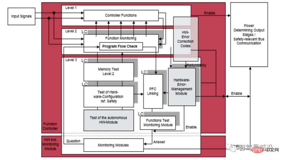
##Figure 2 E-GAS three-layer monitoring architecture solution
Level1 function implementation layer##Level1 is the function implementation layer, which completes specific function implementation, such as for motor controllers In other words, this layer converts the requested torque into the torque output of the motor.
Level2 function monitoring layer Level2 is the function monitoring layer, used to monitor Level1 Whether the function operates normally. The core of Level2 is to design a method to determine whether Level1 is running normally. Although the method of judging whether Level1 is running normally is often related to the function being monitored, different monitored functions have different judgment methods, such as through software diversification and redundancy. However, there are also some judgment methods with wider application, such as rationality check.
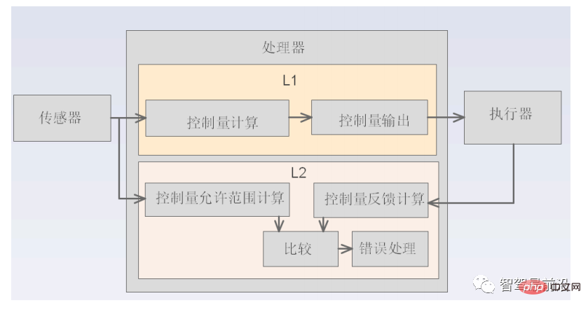
As shown in the figure above, when Level2 uses the rationality verification method to determine whether the Level1 function is operating normally, it first calculates the reasonable range of the allowed output of the control quantity based on the signal input by the sensor, then calculates the actual output quantity fed back from the actuator, and finally determines Whether the actual output volume of Level1 is within the allowed reasonable range. If it is beyond the reasonable range, it is determined that Level1 function is abnormal and error processing is performed.
Level3 controller monitoring layer
Level3 is the controller monitoring layer, mainly composed of Three parts of functional composition.
Electronic and electrical system hardware diagnosis: Monitor electronic and electrical system hardware failures, such as: controller CPU core failure, RAM failure, ROM failure, etc.
Independent monitoring: After a controller-related fault occurs, the controller can no longer reliably execute safety-related logic. In order to ensure safety, additional external independent monitoring modules are required. Ensure that even after a serious failure occurs in the MCU, it can still enter a safe state. This additional independent monitoring module is usually a power management chip with integrated watchdog.
Application flow check: Monitor whether the monitoring programs of Level1 and Level2 are running normally. This monitoring function is implemented by binding program flow inspection and watchdog feeding. If the monitoring programs related to Level1 and Level2 do not run in the set order, or are not executed within the specified time, the program flow check fails and the dog cannot be fed normally, thus entering the system safety state.
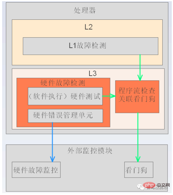
##Figure 4 Level3 functional block diagram
02 The development of functional safety software architecture abroad
When it comes to functional safety and software architecture, we can look at the two dimensions of "software architecture that conforms to functional safety" and "functional safety software architecture" to look at the relationship between them.
The former focuses on the compliance of our software architecture design process with functional safety from a software development perspective, that is, our software architecture design process needs to meet the various requirements proposed by ISO 26262. Requirements, such as: marking methods, design principles, design element requirements, security analysis requirements, error detection mechanism requirements, error handling mechanisms and design verification methods, etc. Among them, the mainstream method of security analysis at the software architecture level is "software FMEA (Failure Mode and Effects Analysis)" and "Software DFA (Dependent Failure Analysis)".
The latter focuses on supporting system-level functional safety from the perspective of embedded software systems. Based on the idea of E-Gas security architecture, we believe that "layered monitoring ideas", "security measures" and "diagnostic framework" are the core of "functional safety software architecture", and "layered monitoring ideas" and "security measures" are above As stated in the article, the rest of this section mainly focuses on the "diagnostic framework". Regardless of whether the basic software development platform we use is AUTOSAR CP, AP or non-AUTOSAR, the design ideas of the functional safety software architecture are similar, and are explained here based on AUTOSAR CP.
1) Technical requirements for functional safety diagnostic framework
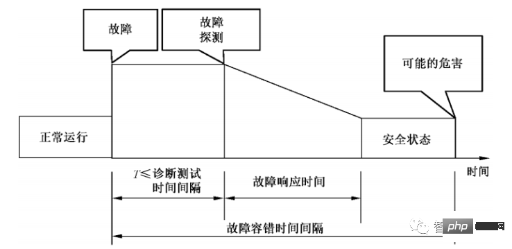
##Figure 5 Fault response time and fault tolerance time interval
We combine FTTI (fault tolerant time interval) to understand the fault diagnosis process. The period from the occurrence of a fault to the occurrence of possible hazards is the FTTI time. During this period, there are mainly diagnostic tests, fault response processes, and the hope of entering a safe state before possible hazards occur (Figure 4.1-8). The diagnostic test process needs to consider diagnostic test triggering, fault confirmation (debounce), etc.The fault response process needs to consider entering a reasonable operating mode (such as: Fail safe, Fail operational, Emergency operation, etc.), fault storage, etc.
2) Interpretation of foreign diagnostic framework technology Before interpreting the diagnostic framework technology, there are two suggestions for reference. ① Suggestion 1: Determine the timing of diagnostic testing based on requirements a. When powering on: Here is an explanation based on a typical application requirement. The safety mechanism and the corresponding functions form a double point. In order to reduce the failure rate of latent multi-point faults, the safety mechanism generally needs to perform self-checking during the system startup phase (when powered on). Additionally, diagnostic test synchronization issues need to be considered in multiprocessor systems. b. Runtime: Generally divided into periodic diagnostic tests and conditional diagnostic tests. The definition of the diagnostic cycle needs to consider the constraints of FDTI (fault detection time interval), and conditional diagnostic tests are generally diagnostics of a function when a state transition occurs or before activating a function. c. When powering off: You can choose to perform some time-consuming tests, and the test results are generally processed at the next startup. ② Recommendation 2: Carry out group diagnostic tests In order to facilitate diagnostic management (including diagnostic triggering and fault response, etc.), according to the critical fault/ Non-critical faults, diagnostic test timing and other factors are grouped. If a critical fault is detected during power-on, such as Core Fault, Ram Test Fault, etc., then the fault response can be processed in a silent state (such as: MCU is in continuous reset state).
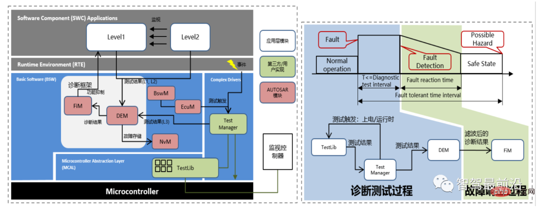
##Figure 6 "Functional Safety Diagnosis Framework" and "Functional Safety Diagnosis Control Flow"
E-Gas three-layer monitoring framework Level1 (function level) and Level2 (function monitoring level) are located in the ASW (application software, that is: SWC in Figure 4.1-9) layer, Level3 (controller monitoring level) is located at the BSW (basic software) layer. The "Diagnostic Framework" is also located at the BSW layer. As mentioned above, it mainly covers diagnostic testing and fault response processes. Its composition and working process are introduced below:
- BswM and EcuM are mainly responsible for power-on and power-off management, and perform diagnostic tests during power-on, run-time, and power-off during the STARTUP, UP, and SHUTDOWN stages respectively
- ASW-Level1 (E-Gas Level1) covers the diagnosis of function input/output; ASW-Level2 (E-Gas Level2) is generally implemented as a redundant algorithm for the ASW-Level1 function and realizes the decomposition of the ASW-Level1 ASIL level; TestLib (E-GasLevel3) monitors hardware failures at the ECU and MCU levels (it is recommended to refer to ISO26262 (2018)-Part5 Annex D and MCU safety manual), covers the diagnosis of Level1 and Level2 common cause failures, and is used with the "monitoring controller" to implement Question and answer watchdog mechanism for logical and time independent diagnosis
- TestManager is responsible for triggering diagnostic tests of the TestLib safety mechanism and collecting corresponding test results
- DEM collects test results of E-Gas Level1/2/3, debounces diagnostic events, marks fault codes and stores fault information through NvM. FiM marks the configured functions based on the DEM diagnostic test results (after debounce), and the function software (ASW-Level1) determines the suppression of the functions based on the marks.
The above is the detailed content of Smart car functional safety software architecture. For more information, please follow other related articles on the PHP Chinese website!

Hot AI Tools

Undresser.AI Undress
AI-powered app for creating realistic nude photos

AI Clothes Remover
Online AI tool for removing clothes from photos.

Undress AI Tool
Undress images for free

Clothoff.io
AI clothes remover

AI Hentai Generator
Generate AI Hentai for free.

Hot Article

Hot Tools

Notepad++7.3.1
Easy-to-use and free code editor

SublimeText3 Chinese version
Chinese version, very easy to use

Zend Studio 13.0.1
Powerful PHP integrated development environment

Dreamweaver CS6
Visual web development tools

SublimeText3 Mac version
God-level code editing software (SublimeText3)

Hot Topics
 1378
1378
 52
52
 The facial features are flying around, opening the mouth, staring, and raising eyebrows, AI can imitate them perfectly, making it impossible to prevent video scams
Dec 14, 2023 pm 11:30 PM
With such a powerful AI imitation ability, it is really impossible to prevent it. It is completely impossible to prevent it. Has the development of AI reached this level now? Your front foot makes your facial features fly, and on your back foot, the exact same expression is reproduced. Staring, raising eyebrows, pouting, no matter how exaggerated the expression is, it is all imitated perfectly. Increase the difficulty, raise the eyebrows higher, open the eyes wider, and even the mouth shape is crooked, and the virtual character avatar can perfectly reproduce the expression. When you adjust the parameters on the left, the virtual avatar on the right will also change its movements accordingly to give a close-up of the mouth and eyes. The imitation cannot be said to be exactly the same, but the expression is exactly the same (far right). The research comes from institutions such as the Technical University of Munich, which proposes GaussianAvatars, which
 MotionLM: Language modeling technology for multi-agent motion prediction
Oct 13, 2023 pm 12:09 PM
This article is reprinted with permission from the Autonomous Driving Heart public account. Please contact the source for reprinting. Original title: MotionLM: Multi-Agent Motion Forecasting as Language Modeling Paper link: https://arxiv.org/pdf/2309.16534.pdf Author affiliation: Waymo Conference: ICCV2023 Paper idea: For autonomous vehicle safety planning, reliably predict the future behavior of road agents is crucial. This study represents continuous trajectories as sequences of discrete motion tokens and treats multi-agent motion prediction as a language modeling task. The model we propose, MotionLM, has the following advantages: First
 Do you know that programmers will be in decline in a few years?
Nov 08, 2023 am 11:17 AM
"ComputerWorld" magazine once wrote an article saying that "programming will disappear by 1960" because IBM developed a new language FORTRAN, which allows engineers to write the mathematical formulas they need and then submit them. Give the computer a run, so programming ends. A few years later, we heard a new saying: any business person can use business terms to describe their problems and tell the computer what to do. Using this programming language called COBOL, companies no longer need programmers. . Later, it is said that IBM developed a new programming language called RPG that allows employees to fill in forms and generate reports, so most of the company's programming needs can be completed through it.
 GR-1 Fourier Intelligent Universal Humanoid Robot is about to start pre-sale!
Sep 27, 2023 pm 08:41 PM
The humanoid robot is 1.65 meters tall, weighs 55 kilograms, and has 44 degrees of freedom in its body. It can walk quickly, avoid obstacles quickly, climb steadily up and down slopes, and resist impact interference. You can now take it home! Fourier Intelligence's universal humanoid robot GR-1 has started pre-sale. Robot Lecture Hall Fourier Intelligence's Fourier GR-1 universal humanoid robot has now opened for pre-sale. GR-1 has a highly bionic trunk configuration and anthropomorphic motion control. The whole body has 44 degrees of freedom. It has the ability to walk, avoid obstacles, cross obstacles, go up and down slopes, resist interference, and adapt to different road surfaces. It is a general artificial intelligence system. Ideal carrier. Official website pre-sale page: www.fftai.cn/order#FourierGR-1# Fourier Intelligence needs to be rewritten.
 Huawei will launch the Xuanji sensing system in the field of smart wearables, which can assess the user's emotional state based on heart rate
Aug 29, 2024 pm 03:30 PM
Recently, Huawei announced that it will launch a new smart wearable product equipped with Xuanji sensing system in September, which is expected to be Huawei's latest smart watch. This new product will integrate advanced emotional health monitoring functions. The Xuanji Perception System provides users with a comprehensive health assessment with its six characteristics - accuracy, comprehensiveness, speed, flexibility, openness and scalability. The system uses a super-sensing module and optimizes the multi-channel optical path architecture technology, which greatly improves the monitoring accuracy of basic indicators such as heart rate, blood oxygen and respiration rate. In addition, the Xuanji Sensing System has also expanded the research on emotional states based on heart rate data. It is not limited to physiological indicators, but can also evaluate the user's emotional state and stress level. It supports the monitoring of more than 60 sports health indicators, covering cardiovascular, respiratory, neurological, endocrine,
 What are the effective methods and common Base methods for pedestrian trajectory prediction? Top conference papers sharing!
Oct 17, 2023 am 11:13 AM
Trajectory prediction has been gaining momentum in the past two years, but most of it focuses on the direction of vehicle trajectory prediction. Today, Autonomous Driving Heart will share with you the algorithm for pedestrian trajectory prediction on NeurIPS - SHENet. In restricted scenes, human movement patterns are usually To a certain extent, it conforms to limited rules. Based on this assumption, SHENet predicts a person's future trajectory by learning implicit scene rules. The article has been authorized to be original by Autonomous Driving Heart! The author's personal understanding is that currently predicting a person's future trajectory is still a challenging problem due to the randomness and subjectivity of human movement. However, human movement patterns in constrained scenes often vary due to scene constraints (such as floor plans, roads, and obstacles) and human-to-human or human-to-object interactivity.
 My smartwatch won't turn on: What to do now
Aug 23, 2023 pm 05:41 PM
What to do if your smartwatch won't turn on? Here are the options available to restore the life of your beloved smartwatch. CHECK POWER PLAY: Imagine a star-studded stage with your smartwatch as the headliner, but the curtains don't rise because it forgot its battery! Before we delve into the details, make sure your smartwatch isn't just running on smoke and mirrors. Give it a proper charge time, and if you're feeling a little extra, give it a stylish new cable - the fashion-forward kind! Fantastic Reboot: When in doubt, give it a little R&R - that's Reboot and Revival! Press and hold these buttons like a maestro conducting a symphony. Different smartwatches have their own reboot rituals — Google is your guide. this is one
 UniOcc: Unifying vision-centric occupancy prediction with geometric and semantic rendering!
Sep 16, 2023 pm 08:29 PM
Original title: UniOcc: UnifyingVision-Centric3DOccupancyPredictionwithGeometricandSemanticRendering Please click the following link to view the paper: https://arxiv.org/pdf/2306.09117.pdf Paper idea: In this technical report, we propose a solution called UniOCC, using For vision-centric 3D occupancy prediction trajectories in CVPR2023nuScenesOpenDatasetChallenge. Existing occupancy prediction methods mainly focus on using three-dimensional occupancy labels


