Intelligent driving requires people from many different majors to work together, and not everyone has a software or automotive software background. In order to allow people with different backgrounds to understand the content of the article to a certain extent, this article tries to use very popular language to describe it, and uses various pictures to illustrate it. This article avoids the use of ambiguous terminology, and all terms are given their precise definitions the first time they appear.
Intelligent The conceptual model of driving simply solves three core questions:
#1. Where am I?
2. Where am I going?
3. How do I get there?
The first question "Where am I?" needs to be solved is the problem of "environment perception" and "positioning". What needs to be understood is the position of the car itself and the static surrounding the position. environment (roads, traffic signs, traffic lights, etc.) and dynamic environment (cars, people, etc.). This has triggered a series of sensing and positioning technical solutions, including various sensors and algorithm systems.
The second question "Where am I going?" In the field of autonomous driving, it is "planning and decision-making". From this, some terms such as "global planning", "local planning", "task planning", "path planning", "behavior planning", "behavioral decision-making", "movement planning", etc. are derived. Due to linguistic ambiguity, some of these terms are Different ways of saying the same meaning, some of which often have similar but slightly different meanings on different occasions.
Regardless of specific terminology, generally speaking, the problem of "planning decision-making" will be broken down into three parts:
1. Planning in a global sense within a certain range (common terms: global planning, path planning, task planning)
2. Divide the results of the first step into multiple stages (commonly used Terms: behavioral planning, behavioral decision-making)
3. Further planning for each stage (common terms: local planning, motion planning)
For these various plans, many algorithm systems for solving problems have been derived.
The third question "How should I go?" generally refers to "controlling execution", that is, the actual implementation of the smallest plan to achieve the purpose of the plan. Specifically in the car, it is often reflected in various control algorithms, and control theory solves these problems.
Because the solutions to these three problems are all algorithmic problems in the final analysis, so in a sense, the core of autonomous driving is the algorithm. In a sense, software architecture must be able to carry these algorithms. Without a good carrying system, no matter how good the algorithm is, it will be useless.
For the sake of convenience, we represent the three issues of the basic conceptual model as E, P, X respectively , respectively representing environment (Environment), plan (Plan), and execution (eXecute). Each set of E-P-X has its descriptive problem space.
For example, we define problem space A as "driving from Beijing to Guangzhou", then for problem E: its positioning focus may be on the current district in Beijing, and there is no need to refine it to street. We also need to care about whether there are thunderstorms and road structure information above provincial highways. For question P:
P-1: The first step is to design a global path, which highway, national highway, and provincial highway to take
P-2: Plan a series of behaviors based on the global path, including which highway intersection to go to first, how many kilometers to drive, going to the service area to refuel, changing to another road, etc.
P-3: Plan the specific road path to each section. For example, whether you want to take the third or fourth ring road to a highway intersection, which way to change
X must execute every step planned by P.
If we define problem space B as "driving safely through an intersection", then for problem E, we should pay attention to the current road information, traffic light information, vehicle conditions on the road, pedestrian conditions, etc. For P question:
P-1: The first step is to plan a safe path through the intersection, including planning which lane to reach the current intersection according to traffic rules and road information, and entering the target intersection. which lane.
P-2: The second step is to plan a series of action sequences based on the root results of the first step, such as slowing down first, switching the target lane, stopping and waiting for the red light, starting to accelerate, passing intersection.
P-3: The third step is to design a specific trajectory for each action in the second step. The trajectory must be able to avoid obstacles such as pedestrians and vehicles.
X is responsible for executing the output of problem P.
This problem space B is the closest to the problem to be solved by usual planning algorithms. The first step of P-1 is often called "global planning" or "task planning", P-2 is often called "behavioral planning" or "behavioral decision-making", and P-3 is called "local planning" or "behavioral planning". Motion Plan”. As shown in the figure below, E-P-X forms an abstract basic conceptual model, and problem spaces A and B are its specific implementations in a certain scope.
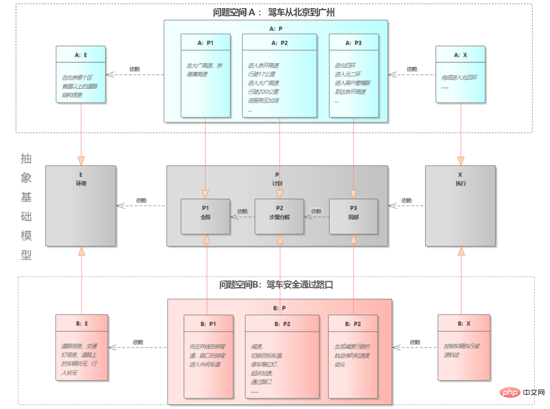
Figure 1 Two EPX problem spaces
A and B Both problem spaces have similar E-P-X structures, but the problems they solve span very different time and space spans. In the picture above, the task that A: So in fact, as shown in the figure below, the E-P-X model is a fractal recursive structure.
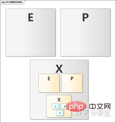
Figure 2 Fractal recursive structure of EPX
Previous level X can always be decomposed into smaller-grained E-P-X again by the next level for execution.
"Fractal" is also called "self-similar fractal". Its popular understanding is that the parts of things have similar structures to the whole, which is symmetry on different scales, such as a tree. A branch of a tree has a similar structure to the entire tree, and furthermore, the stem veins of each leaf also have a similar structure. The figure below lists some typical fractal structures.
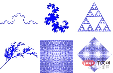
Figure 3 Fractal Example
These 6 graphics have a Characteristics, any part of each figure has the same structure as the entire figure. If you zoom in further on the local area, you will find that the local area has the same structure. Therefore, when we have a set of business processing logic that can be applied to the whole, it can also be applied to parts. Just like the cultivation of some trees, you can take a branch and plant it, and it will grow into a new tree. The expression mapped to a software program is "recursion". This does not mean using recursive functions, but architectural-level recursion.
The more academic expression of "fractal" is "the use of fractional dimension perspective and mathematical methods to describe and study objective things, jumping out of one-dimensional lines, two-dimensional surfaces, and three-dimensional The traditional barriers of three-dimensional and even four-dimensional space and time are closer to the description of the real attributes and states of complex systems, and more in line with the diversity and complexity of objective things." When we find a suitable mathematical expression for "physical reality" and then convert it into "program reality", we can find a more concise, clear, and accurate software architecture and implementation method.
E-P-X is a structure abstracted based on "physical reality". And most of them are various kinds of algorithmic work. Research and development of the individual algorithms themselves can be carried out independently based on predefined input and output conditions. But how to combine the algorithms, trigger them correctly at the right time, and use the results reasonably to finally form a function with practical use. The core of this bridge from "physical reality" to "program reality" is software architecture.
The autonomous driving system goes from Level 1 to Level 5. The higher up, the more deeply the above-mentioned E-P-X model is nested. Software architecture becomes more difficult. Most single Level1 and Level2 functions require only one layer of the E-P-X model. Take AEB (automatic emergency braking) as an example:
E part (perception): mainly static recognition and classification of targets ahead (cars, people), dynamic tracking, detection distance and speed.
P Part: Because AEB only performs longitudinal control, it can all be realized through speed control. So just plan for the speed over a period of time.
PartX: Leave speed planning to the vehicle control unit.
It does not mean that with only one layer of EPX, the AEB function will be simple. In fact, it is very difficult to implement AEB functions that can be mass-produced. However, the first-level EPX does not need to be scheduled based on scenarios. It only needs to focus on the implementation of EPX in a single scenario, and its software architecture is relatively simple. Chapter 2 will introduce the common software architecture of L2 functions.
Even in the EPX cycle at the smallest granularity level, not one EXP implementation can solve all problems at this level.
For example: For a simple straight-line driving use case, we can implement the end X unit as a vehicle control algorithm. This algorithm handles all flat roads, uphill, and downhill scenarios. . You can also use a scheduling unit (S) to identify flat roads, uphill slopes, and downhill slopes as different scenarios based on the information of the E unit, and switch to different next-level EXP cycles. Each EXP loop of the next level implements a single scene. In fact, even if an X unit control algorithm is used to solve all flat road, uphill, and downhill scenarios, the algorithm will still distinguish these scenarios internally. In fact, it is still a small-grained EXP loop.
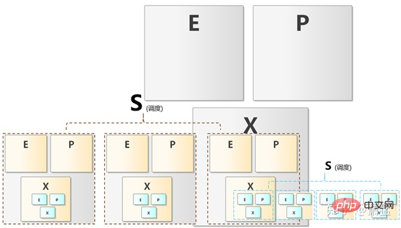
Figure 4 EPX scheduling
As shown in Figure 4, Scene scheduling (S) can be done at every level, which means that the definition of "scenario" also has granular divisions. Therefore, the EPX model should be the EPX-S model. There is just no obvious S section below L2.
Automatic parking assistance functions have begun to require scene scheduling, such as vertical parking, vertical parking, and horizontal parking. Exiting, horizontal parking, diagonal parking, etc. are all different scenarios, and the P and X parts need to be implemented separately. However, scene scheduling can be manually selected through the HMI interface, which is a "human-in-the-loop" S unit.
Level 3 Among the above functions, manual intervention is not required for a long period of continuous driving. It will inevitably involve automatic scheduling of multiple different EXP levels. In this way, the software architecture is very different from the functions below L2. This is one of the reasons why many companies divide L2 and L3 into two different teams.
In fact, as long as the software architecture is consciously designed based on the multi-level EXP-S model, each EXP-S unit has its appropriate embodiment, and it can actually be realized. The set of software architecture supports basic autonomous driving from L1 to L3 and above. It is just that the S unit is weaker for functions below L2, but its architectural status still exists.
Let’s first take a look at the common software architecture of the L2 function. Let’s talk about the commonly used
The three functions of AEB/ACC/LKA are the most classic driving assistance functions of L2, a general system solution The perception part mostly uses a forward-facing camera to output target (vehicles, pedestrians) information, and fuses it with the target data given by the forward-facing millimeter wave radar to obtain more accurate speed and distance. Visual perception and radar perception mostly use Smart Sensor solutions, so Tier 1 can choose products from mature Tier 2 suppliers. The main development work of Tier 1 is on the implementation of perception fusion and functional state machine and vehicle control algorithm.
Option 1: The visual perception results are transferred to the radar perception controller, and the radar perception controller completes perception fusion and L2 functional state machine
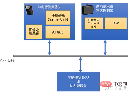
Figure 5 Topology of Option 1
Option 2: Independent L2 controller Smart Sensor connecting vision and radar, L2 controller completes perception fusion and L2 functional state machine
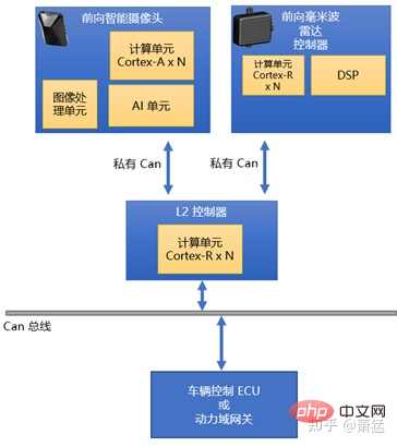
Figure 6 Scheme 2 topology
Both solutions are often used. Solution 1 uses a higher-performance radar controller and allocates some computing units to implement the fusion algorithm and functional state machine. Many chip manufacturers take this part of the computing power into consideration when designing radar processing chips. For example, NXP's S32R series is specially designed for radar ECUs. Its multiple cores are enough to perform radar signal processing and L2 function implementation at the same time. After all, the most computationally intensive visual algorithm is completed on another device.
Option 2 separates L2 to implement the L2 function controller, and obtains sensing data through private Can communication with two Smart Sensors. Generally speaking, this solution can consider adding more L2 functions in the future, and if necessary, you can connect more Smart Sensors.
For the system architecture using Smart Sensor, the forward-facing smart camera and the forward-facing millimeter wave radar respectively provide their respective observed environments. The semantics of the target object in . These two parts of data are directly transferred to the module responsible for perception fusion and L2 function implementation through the Can bus or the internal IPC (inter-process communication of computer OS) mechanism.
Whether it is hardware solution one or solution two, the most commonly used software architecture in the industry is developed based on Classic AutoSar. Classic AutoSar provides common functions for vehicle ECUs and provides execution environment and data input and output channels for reference software. The perception fusion module and other ACC/AEB/LKA functions can be implemented as one or more AutoSar SWCs (software components). Each developer has its own reasonable logic as to whether and how to split these SWC components. But the basic architecture is much the same.
Of course, you can not use Classic AutoSar and use other suitable RTOS as the underlying system. It may be more difficult to develop general functions and meet functional safety standards for vehicle ECUs, but in The architecture of application function development is not much different from the solution using Classic AutoSar.
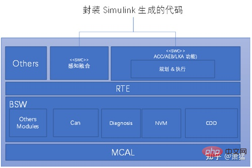
##Figure 7 Typical software architecture of ACC/AEB/LKA
MBD development method
The MBD (model-based development) method is commonly used in the industry to implement perception fusion algorithms, planning and control execution algorithms, and ACC/AEB/LKA functional status machine. Then use tools to generate C code and manually integrate it into the target platform. One of the conveniences of the MDB development method is that you can first use model tools and equipment such as CanOE to directly develop and debug on the vehicle, or connect to the simulation platform for development and debugging. In this way, the development team can be divided into two parts, one part uses model tools to develop application functions, and the other part develops a series of tedious tasks required by all vehicle ECUs, and then integrates them together.
Generally, fully automatic parking products will adopt a more integrated solution, integrating the vision algorithm (static Obstacle recognition, dynamic obstacle recognition, pedestrian recognition, parking space line recognition) ultrasonic radar algorithm (distance detection, obstacle detection) trajectory planning and control execution of the parking process are all completed in one controller. A higher level of integration will also support the 360-degree surround view function in the automatic parking controller, which also needs to support the correction of the camera surround image and the splicing of 2D/3D graphics rendering video output HMI generation and other functions.
The schematic hardware topology is as follows.
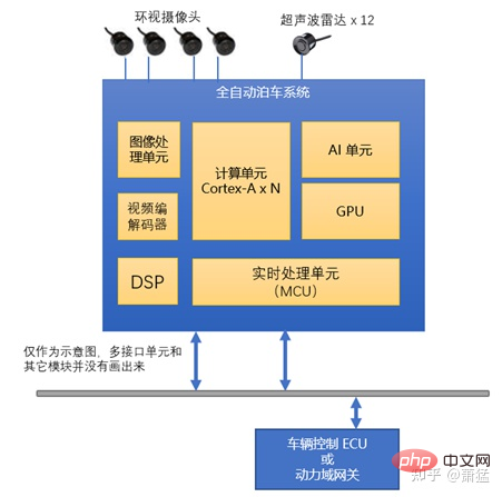
##Figure 8 Hardware topology scheme of parking system
Each module in the figure has different distribution modes in different hardware selection solutions. Generally, MCUs used for real-time processing use a separate chip. Different chip manufacturers have their own AI unit solutions. Some use high-performance DSP, some use proprietary matrix computing units, some use FPGA, and so on.
Typical software architectureThe following figure is a typical software architecture of the automatic parking system (it is just a simplified representation, the actual mass production system will be more complex) :
Compared with 2.1.1, the most significant change here is the distinction between the "real-time domain" and the "performance domain" systems. Generally speaking, we call the software and hardware systems on MCU or other real-time cores (Cortex-R, Cortex-M or other equivalent series) the "real-time domain". The large core in the SOC (Cortex-A or equivalent series) and the Linux/QNX running on it are collectively called the performance domain, which generally also includes software and hardware systems that support visual algorithm acceleration.
Although in terms of engineering difficulty for mass production, the fully automatic parking system is much smaller than Level 2 active safety functions such as ACC/AEB/LKA. But in terms of software architecture, the parking system is much more complicated. Mainly reflected in the following aspects:
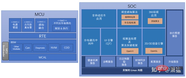
Figure 9 Software architecture of the parking system
The division of real-time domain and performance domain brings systemic complexity, and it is necessary to select different hardware platforms for different calculations based on real-time requirements and computing resource requirements
In addition, through this software architecture, we can see that the introduction of Linux (or QNX/vxworks) brings some questions. These systems themselves are computer operating systems that have nothing to do with specific industries. When used in automotive electronic controllers, there will be a series of general functions that have nothing to do with specific product functions but need to be implemented as automotive ECUs. Such as diagnostics, clock synchronization, upgrades, etc. This part accounts for a very large workload in the overall controller development, exceeding 40% in many cases, and is very related to the reliability of the controller.
In the field of network communication equipment, these are often called management planes. Many are also basic capabilities provided by AutoSar AP. In fact, whether it is CP AutoSar or AP AutoSar, except for the module responsible for communication, most of the others are management plane capabilities.
How to work together if there are multiple L2 functions on a vehicle. The figure below is an example of a simplified multi-controller topology.
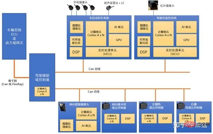
Figure 10 Topology scheme of multiple L2 function controllers plus domain controllers
Six controllers are integrated in this topology. The functions provided by "Fully Automatic Parking System", "Forward-facing Smart Camera" and "Forward-facing Millimeter Wave Radar" are as mentioned earlier. The left and right corner radars are two mirrored devices, each operating independently can realize functions such as "rear vehicle approaching alarm" and "door opening alarm". The "driver monitoring system" detects the driver's status and can give an alert when it finds that the driver is tired while driving. If the driver completely loses the ability to move, it will notify other systems to try to slow down and pull over.
There are the following key points in this topology: introducing a domain controller to connect multiple independent driving assistance function controllers, and connecting the domain controller to the backbone network; multiple Can buses in the driving assistance domain, Avoid insufficient bus bandwidth.
In terms of software architecture, each driving assistance controller operates independently and independently decides to start and stop its own functions. Relevant control signals are sent to the domain controller, which forwards them to the power domain. The driver assistance domain controller is responsible for adjudicating the control outputs of the individual controllers. From the perspective of the role that domain controllers can play here, there are various possible designs from light to heavy. In the lightweight domain controller design, the domain controller only does simple data forwarding, filtering the data on the backbone network and sending it to the controller in the domain. Send control signals from controllers in the domain to the backbone network. This method does not require high computing power of the domain controller.
If the domain controller takes on more work, it can take over the calculation work of the real-time domain part of other controllers. For example, the planning control calculations of ACC/AEB/LKA are all performed on the domain controller. This requires other controllers to send sensing data to the domain controller, which will be processed uniformly by the domain controller. This requires higher computing power. At the same time, the bandwidth requirements for intra-domain networks have also increased.
Go further, because it can get all the sensing data, the domain controller can also develop some additional functions, such as relying on the sensors in the picture, it may be in the domain controller Realize the function of lane change assistance or emergency obstacle avoidance.
As functions are gradually concentrated on domain controllers, the non-aware parts of other controllers that bear the sensing part are gradually weakened.
Arbitration Mechanism
Before Speaking of, the realization of ACC/AEB/LKA functions, the realization of fully automatic parking, and other functions below a single L2 can all be understood as a one- or two-layer fractal recursive EPX-S model.
In fact, the three functions of ACC/AEB/LKA can be turned on at the same time in actual mass-produced products, and each is a separate EPX-S cycle. This means that multiple EPX-S loops can be run simultaneously and in parallel. If X output is generated at the same time, it needs to be arbitrated by an arbitration mechanism (Arbitration).
When multiple controllers are running at the same time, the domain controller arbitrates at a higher level.
So the EPX-S model should be extended to the EPX-SA model. As shown in the figure below, Scenario 1 and Scenario 2 are two EPX-S loops running in parallel, and the X they generate is output after arbitration.
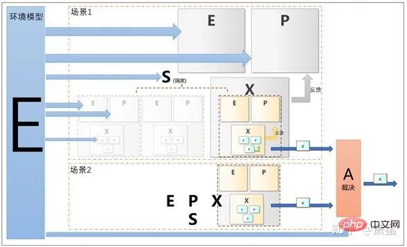
##Figure 11 EPX-SA Concept Model
Environment Proposition of model concept
Each controller that implements a single L2 function has certain aspects of perception capabilities. They all describe a certain aspect of the attributes of the vehicle's internal and external environment, which can be divided from spatial angles and distances, or from physical attributes, such as visible light, ultrasonic waves, millimeter waves, and lasers. If an ideal and completely accurate 3D model system is established for the entire environment, each sensor is equivalent to a filter for this model. Like "the blind man touching the elephant", each sensor expresses a certain aspect of the ideal model's attributes.
The perception part of intelligent driving is actually to use as many sensors and algorithms as possible to achieve an approximation to the ideal model. The more sensors available, the more accurate the algorithm will be and the less it will deviate from the ideal model.
In the domain controller of L2, if necessary, the sensing data of all lower-level controllers can be obtained. Then at this level, an ideal value can be spelled out based on all the sensing results. Although the realistic model of the environmental model is still far from the ideal model, it is already an environmental model in the overall sense.
The information provided by the environment model is not only used in the planning modules (P) at all levels, but also in the scheduling (S) and arbitration (A) phases.
The above is the detailed content of Learn the intelligent driving domain controller software architecture in one article. For more information, please follow other related articles on the PHP Chinese website!
 Page replacement algorithm
 js gets current time
 What does pycharm mean when running in parallel?
 css3transition
 Introduction to the main work content of front-end engineers
 How to connect php to mssql database
 The difference between Hongmeng system and Android system
 How to open the download permission of Douyin
 tim mobile online


