
 Operation and Maintenance
Safety
How to analyze juniper switch ex2200 configuration and simple commands
Operation and Maintenance
Safety
How to analyze juniper switch ex2200 configuration and simple commands
How to analyze juniper switch ex2200 configuration and simple commands

qnqy-dpf-jrex2200-01# show | display set
set version 12.3R11.2
set system host-name qnqy-dpf-jrex2200-01
set system time-zone Asia/Shanghai
set system root-authentication encrypted-password "$1$7RMyTyeG$tLGAToBggMFhcOw85Ts.EP/"
set system login user admin uid 2000
set system login user admin class super-user
set system login user admin authentication encrypted-password "$1$m5Fp3PtY$cenAvv5Yq6VKsAlA317C2E/"
set system services ftp
set system services ssh
set system services telnet
set system services web-management https system-generated-certificate
set system services web-management https interface all
set system syslog user * any emergency
set system syslog file messages any notice
set system syslog file messages authorization info
set system syslog file interactive-commands interactive-commands any
set system ntp boot-server 192.168.16.45
set system ntp server 192.168.16.45
set chassis alarm management-ethernet link-down ignore
set chassis auto-image-upgrade
set interfaces interface-range allport member-range ge-0/0/0 to ge-0/0/20
set interfaces interface-range allport unit 0 family ethernet-switching port-mode access
set interfaces interface-range allport unit 0 family ethernet-switching vlan members vlan_54
set interfaces interface-range allport unit 0 family ethernet-switching filter input 54
deactivate interfaces interface-range allport unit 0 family ethernet-switching filter
set interfaces ge-0/0/0 unit 0 family ethernet-switching
set interfaces ge-0/0/1 unit 0 family ethernet-switching
set interfaces ge-0/0/2 unit 0 family ethernet-switching
set interfaces ge-0/0/3 unit 0 family ethernet-switching
set interfaces ge-0/0/4 unit 0 family ethernet-switching
set interfaces ge-0/0/5 unit 0 family ethernet-switching
set interfaces ge-0/0/6 unit 0 family ethernet-switching
set interfaces ge-0/0/7 unit 0 family ethernet-switching
set interfaces ge-0/0/8 unit 0 family ethernet-switching
set interfaces ge-0/0/9 unit 0 family ethernet-switching
set interfaces ge-0/0/10 unit 0 family ethernet-switching
set interfaces ge-0/0/11 unit 0 family ethernet-switching
set interfaces ge-0/0/12 unit 0 family ethernet-switching
set interfaces ge-0/0/13 unit 0 family ethernet-switching
set interfaces ge-0/0/14 unit 0 family ethernet-switching
set interfaces ge-0/0/15 unit 0 family ethernet-switching
set interfaces ge-0/0/16 unit 0 family ethernet-switching
set interfaces ge-0/0/17 unit 0 family ethernet-switching
set interfaces ge-0/0/18 unit 0 family ethernet-switching
set interfaces ge-0/0/19 unit 0 family ethernet-switching
set interfaces ge-0/0/20 unit 0 family ethernet-switching
set interfaces ge-0/0/21 unit 0 family ethernet-switching port-mode access
set interfaces ge-0/0/21 unit 0 family ethernet-switching vlan members 917
set interfaces ge-0/0/22 unit 0 family ethernet-switching port-mode access
set interfaces ge-0/0/22 unit 0 family ethernet-switching vlan members vlan_54
set interfaces ge-0/0/23 unit 0 family ethernet-switching port-mode trunk
set interfaces ge-0/0/23 unit 0 family ethernet-switching vlan members all
set interfaces ge-0/1/0 unit 0 family ethernet-switching port-mode trunk
set interfaces ge-0/1/0 unit 0 family ethernet-switching vlan members all
set interfaces ge-0/1/2 unit 0 family ethernet-switching
set interfaces ge-0/1/3 unit 0 family ethernet-switching
set interfaces vlan unit 0
set interfaces vlan unit 502 family inet address 192.168.13.171/24
set snmp community public authorization read-only
set routing-options static route 0.0.0.0/0 next-hop 192.168.13.254
set protocols igmp-snooping vlan all
set protocols rstp bridge-priority 60k
set protocols rstp interface allport edge
set protocols vstp vlan vlan_502
set protocols vstp vlan vlan_54
set protocols lldp interface all
set protocols lldp-med interface all
set firewall family inet filter RE_Filter term 1 from source-address 192.168.16.0/24
set firewall family inet filter RE_Filter term 1 from protocol tcp
set firewall family inet filter RE_Filter term 1 from destination-port telnet
set firewall family inet filter RE_Filter term 1 from destination-port ssh
set firewall family inet filter RE_Filter term 1 from destination-port http
set firewall family inet filter RE_Filter term 1 from destination-port ftp
set firewall family inet filter RE_Filter term 1 from destination-port https
set firewall family inet filter RE_Filter term 1 then accept
set firewall family inet filter RE_Filter term 2 from protocol tcp
set firewall family inet filter RE_Filter term 2 from destination-port telnet
set firewall family inet filter RE_Filter term 2 from destination-port ssh
set firewall family inet filter RE_Filter term 2 from destination-port http
set firewall family inet filter RE_Filter term 2 from destination-port ftp
set firewall family inet filter RE_Filter term 2 from destination-port https
set firewall family inet filter RE_Filter term 2 then discard
set firewall family inet filter RE_Filter term icmp from source-address 192.168.16.0/24
set firewall family inet filter RE_Filter term icmp from protocol icmp
set firewall family inet filter RE_Filter term icmp then accept
set firewall family inet filter RE_Filter term icmp-other from protocol icmp
set firewall family inet filter RE_Filter term icmp-other then discard
set firewall family inet filter RE_Filter term NTP from source-address 192.168.16.45/32
set firewall family inet filter RE_Filter term NTP from protocol tcp
set firewall family inet filter RE_Filter term NTP from protocol udp
set firewall family inet filter RE_Filter term NTP from source-port ntp
set firewall family inet filter RE_Filter term NTP-Other from protocol tcp
set firewall family inet filter RE_Filter term NTP-Other from protocol udp
set firewall family inet filter RE_Filter term NTP-Other from source-port ntp
set firewall family inet filter RE_Filter term NTP-Other then discard
set firewall family inet filter RE_Filter term Other then accept
set firewall family ethernet-switching filter 54 term 1 from protocol udp
set firewall family ethernet-switching filter 54 term 1 from destination-port 1434
set firewall family ethernet-switching filter 54 term 1 from destination-port 1433
set firewall family ethernet-switching filter 54 term 1 from destination-port netbios-ns
set firewall family ethernet-switching filter 54 term 1 from destination-port netbios-dgm
set firewall family ethernet-switching filter 54 term 1 from destination-port 139
set firewall family ethernet-switching filter 54 term 1 from destination-port netbios-ssn
set firewall family ethernet-switching filter 54 term 1 then discard
set firewall family ethernet-switching filter 54 term 2 from protocol tcp
set firewall family ethernet-switching filter 54 term 2 from destination-port 135
set firewall family ethernet-switching filter 54 term 2 from destination-port 139
set firewall family ethernet-switching filter 54 term 2 from destination-port 445
set firewall family ethernet-switching filter 54 term 2 then discard
set firewall family ethernet-switching filter 54 term Other-Permit then accept
set ethernet-switching-options secure-access-port interface ge-0/0/23.0 dhcp-trusted
set ethernet-switching-options secure-access-port interface ge-0/1/0.0 dhcp-trusted
set ethernet-switching-options secure-access-port interface allport mac-limit 10
set ethernet-switching-options secure-access-port interface allport mac-limit action shutdown
set ethernet-switching-options secure-access-port interface allport vlan 54 mac-limit 10
set ethernet-switching-options secure-access-port interface allport vlan 54 mac-limit action drop
set ethernet-switching-options secure-access-port interface allport no-dhcp-trusted
set ethernet-switching-options secure-access-port vlan vlan_54 arp-inspection
set ethernet-switching-options secure-access-port vlan vlan_54 examine-dhcp
set ethernet-switching-options secure-access-port vlan vlan_54 ip-source-guard
set ethernet-switching-options port-error-disable disable-timeout 600
set ethernet-switching-options storm-control interface all
set ethernet-switching-options bpdu-block interface allport
set vlans default l3-interface vlan.0
set vlans vlan917 vlan-id 917
set vlans vlan_502 vlan-id 502
set vlans vlan_502 l3-interface vlan.502
set vlans vlan_506 vlan-id 506
set vlans vlan_54 vlan-id 54
set vlans vlan_924 description guanli-vlan
set vlans vlan_924 vlan-id 924
简单命令
login: root
password :
登录后 输入 cli ;config;show | disp set 查看和配置
root@qnqy-dpf-jrex2200-01:RE:0% cli
{master:0}
root@qnqy-dpf-jrex2200-01> configure
Entering configuration mode
{master:0}[edit]
root@qnqy-dpf-jrex2200-01# show | display set
set version 12.3R11.2
set system host-name qnqy-dpf-jrex2200-01
set system time-zone Asia/Shanghai
set system root-authentication encrypted-password ""
set system login user admin uid 2000
set system login user admin class super-user
set system login user admin
………………
把ge0/0/0 从vlan809设置成vlan917
root@qnqy-dpf-jrex2200-01#et interfaces ge-0/0/0 unit 0 family ethernet-switching port-mode access
{master:0}[edit]
root@qnqy-dpf-jrex2200-01# delete interfaces ge-0/0/0 unit 0 family ethernet-switching vlan members 809
{master:0}[edit]
root@qnqy-dpf-jrex2200-01# set interfaces ge-0/0/0 unit 0 family ethernet-switching vlan members 917
If you want To delete a vlan, be sure to clear the associated ports first and then delete them. After all changes are completed, commit must be submitted to take effect.
configuration check succeeds
commit complete
Configuration management address, Interface vlan, to enter port mode, set the vlan502 interface management address 192.168.13.171
root@qnqy-dpf-jrex2200-01# edit interfaces
{master:0}[edit interfaces]
root@qnqy-dpf-jrex2200-01#set vlan unit 502 family inet address 192.168.13.171/24
top Return to global binding vlan layer 3 interface
root @qnqy-dpf-jrex2200-01#set vlans vlan_502 l3-interface vlan.502
Restart
root> request system reboot
View serial number and optical port hardware information
root> show chassis hardware
ping command
root >ping 192.168.127.254
View alarm information and temperature
root>show chassis alarms
root>show chassis environment
The above is the detailed content of How to analyze juniper switch ex2200 configuration and simple commands. For more information, please follow other related articles on the PHP Chinese website!

Hot AI Tools

Undresser.AI Undress
AI-powered app for creating realistic nude photos

AI Clothes Remover
Online AI tool for removing clothes from photos.

Undress AI Tool
Undress images for free

Clothoff.io
AI clothes remover

AI Hentai Generator
Generate AI Hentai for free.

Hot Article
Hot Tools

Notepad++7.3.1
Easy-to-use and free code editor

SublimeText3 Chinese version
Chinese version, very easy to use

Zend Studio 13.0.1
Powerful PHP integrated development environment

Dreamweaver CS6
Visual web development tools

SublimeText3 Mac version
God-level code editing software (SublimeText3)
Hot Topics
 1382
1382
 52
52

 How to implement Juniper JunOS PPPOE configuration
May 17, 2023 pm 05:55 PM
How to implement Juniper JunOS PPPOE configuration
May 17, 2023 pm 05:55 PM
1) Select interface fe-0/0/1 as the physical interface of the PPPOE dial-up interface, and encapsulate it into pppoesesetinterfacesfe-0/0/1unit0encapsulationppp-over-ether2) Configure the PP0.0 parameters of the PPPOE interface setinterfacespp0unit0pppoe-optionsunderlying-interfacefe-0/ 0/1.0setinterfacespp0unit0pppoe-optionsidle-timeout0setinterfacespp0unit0pppoe-
 Broadcom Unveils Innovation, Launches Industry's First On-Chip Neural Network Switch
Dec 03, 2023 pm 08:51 PM
Broadcom Unveils Innovation, Launches Industry's First On-Chip Neural Network Switch
Dec 03, 2023 pm 08:51 PM
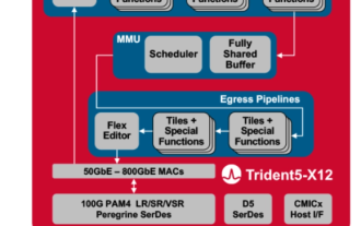
Broadcom recently announced the launch of the Trident5-X12 chip, which is equipped with a new NetGNT (Network General Neural Network Traffic Analyzer) on-chip neural network inference engine. NetGNT is different from traditional packet processing. It can work in parallel to enhance standard packet processing. pipeline. Traditional pipelines can only process one packet/path at a time, while NetGNT, as a machine learning inference engine, can be trained to identify various traffic patterns across the entire chip. It is understood that the Trident5-X12 chip has powerful software programming functions and on-site upgrade functions, providing a bandwidth of up to 16.0 Terabits/second, which is twice that of Trident4-X9. In addition, the new chip also supports
 How does a switch work?
Dec 26, 2023 am 11:56 AM
How does a switch work?
Dec 26, 2023 am 11:56 AM
The working principle of the switch includes: 1. Data frame reception and analysis; 2. Forwarding table update; 3. Data frame forwarding; 4. Flood processing; 5. Connection maintenance. Detailed introduction: 1. Data frame reception and parsing. When the switch receives a data frame, it will first parse the data frame and extract the source MAC address and destination MAC address and other information; 2. Update of the forwarding table, The switch maintains a forwarding table internally, which records the correspondence between MAC addresses and interfaces; 3. Forwarding of data frames, etc.
 Learn more about the dis command in switch inspection
Feb 18, 2024 am 10:05 AM
Learn more about the dis command in switch inspection
Feb 18, 2024 am 10:05 AM
What is the dis command used in switch inspection? In the maintenance and management process of network equipment, switches are an indispensable part. Inspection of switches is one of the important links to ensure the normal operation of the network. During the inspection process, the dis command is a commonly used command on switches. The purpose and function of the dis command will be introduced in detail below. dis is the abbreviation of display. It is a commonly used command on Huawei switch equipment and is used to display various information of the equipment. The dis command can display the configuration information and operating status of the switch.
 How does a switch work?
Dec 26, 2023 pm 02:07 PM
How does a switch work?
Dec 26, 2023 pm 02:07 PM
The working principle of the switch is based on the second layer of the OSI reference model, the data link layer. A switch is a network device based on a learning process that enables communication between different devices in the network by parsing and forwarding data frames. The switch can continuously improve the contents of its internal forwarding table, improve the efficiency and reliability of data exchange, and ensure the stability and security of the connection. Switches are widely used in enterprise networks, data centers, campus networks and other scenarios to provide stable and efficient connection services for various applications.
 What are the three authentication mode configurations of H3C switch telnet service?
May 21, 2023 pm 07:40 PM
What are the three authentication mode configurations of H3C switch telnet service?
May 21, 2023 pm 07:40 PM
The following takes an H3C switch as an example to introduce the three authentication methods of telnet service. Configuration steps for None authentication mode: [H3C] telnetserverenable//Enable Telnet service [H3C] user-interfacevty04//Allow remote users 0-4, a total of 5 accounts at the same time Log in [H3C-line-vty0-4] authentication-modenone//Authentication mode is none, no authentication is required [H3C-line-vty0-4] user-rolelevel-3//Set login user permissions Password authentication mode configuration steps: [ H3C]telne
 What are the main functions of a switch?
Aug 18, 2022 pm 02:56 PM
What are the main functions of a switch?
Aug 18, 2022 pm 02:56 PM
The main functions of the switch are physical addressing, network topology, error checking, frame sequence and flow control; the switch is a network device used for electro-optical signal forwarding, and also has some new functions such as support for virtual LAN, Support for link aggregation, and some even have firewall functions.
 What is the difference between a switch and a router
Jan 16, 2024 pm 03:39 PM
What is the difference between a switch and a router
Jan 16, 2024 pm 03:39 PM
Differences: 1. Different working principles: The switch works at the relay layer and is mainly addressed based on MAC address. The router works at the network layer, addresses according to the IP address, and can handle the TCP/IP protocol; 2. Different functions: the switch can make multiple computers connected to it form a local area network, but it cannot automatically identify the address where the data packet is sent and arrived. The router is responsible for automatically identifying the addresses where data packets are sent and arrived, and can handle the routing of data packets; 3. Different usage scenarios: Routers are usually used for sending and receiving in one place. A switch is used to connect multiple computers.
