
 Technology peripherals
AI
An article talks about the time stamp synchronization problem of lidar and camera calibration
Technology peripherals
AI
An article talks about the time stamp synchronization problem of lidar and camera calibration
An article talks about the time stamp synchronization problem of lidar and camera calibration

01 Camera Features - Exposure and Readout
The camera acquires a frame of image in two stages: exposure and readout. Depending on the sensor used by the camera, the overlapping relationship between the camera's exposure time and readout time is also different, which can be divided into overlapping exposure and non-overlapping exposure.
Compared with non-overlapping exposure, overlapping exposure can reduce the impact of exposure time on the drawing time.
Rewritten sentence: After the exposure and readout of the current frame are completed, the exposure and readout of the next frame are performed. This is a non-overlapping exposure. The non-overlapping exposure frame period is greater than the sum of the exposure time and the frame readout time.
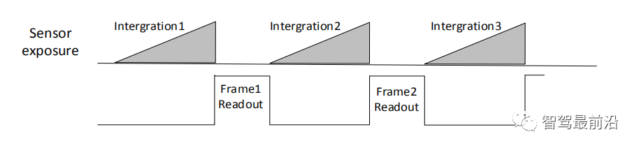
Inner trigger mode non-overlapping exposure
Overlapping exposure means that the exposure of the current frame partially overlaps with the readout process of the previous frame, that is, the exposure of the next frame has begun, while the readout of the previous frame is still in progress. The overlapping exposure frame period is less than or equal to the sum of the exposure time and the frame readout time.
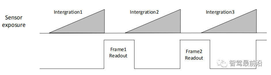
Internal trigger mode overlapping exposure
Yes! The purpose of the previous paragraph is to tell you: don’t be surprised whether the exposure time of the current frame overlaps with the readout time of the previous frame in the following description.
02 Image acquisition: trigger mode (external input)
The trigger mode of the camera is divided into two types: internal trigger mode and external trigger mode.
Internal trigger mode: The camera collects images through the signal given inside the device.
External trigger mode: The camera collects images through external signals. Soft trigger and hardware trigger are the two main forms of external signals. External signals can be either software signals or hardware signals. The external trigger mode is as shown in the figure:
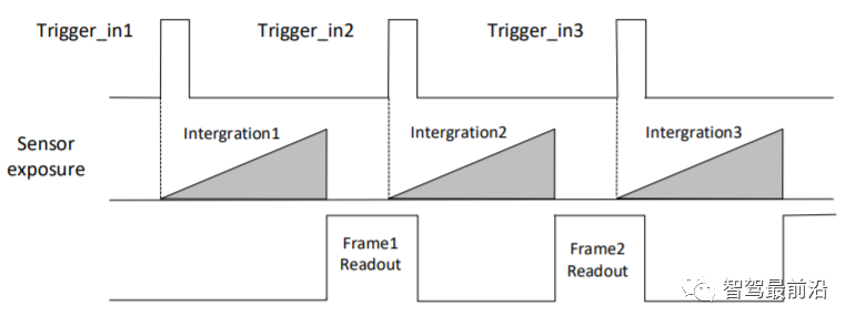
External trigger mode
Soft trigger : The trigger signal is sent by the software (you can also use the API interface provided by the camera SDK for soft triggering).
When using hardware trigger, the camera will connect to the external device through its I/O interface and receive the trigger pulse signal from the external device to collect images. In fact, it directly reads and writes the internal registers of the camera. The picture below is the 6-pin cable of the power IO of the Hikvision camera:
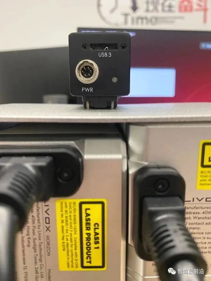
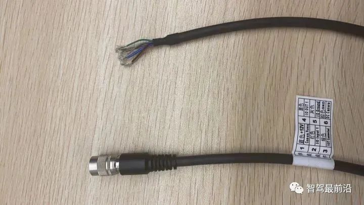
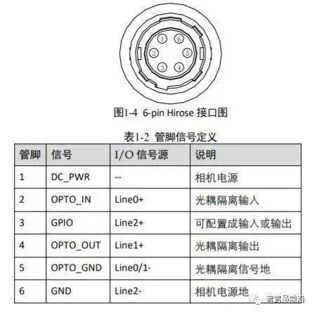
##Haikang camera power supply and IO interface (6-pin Hirose)
Among them, Hikvision camera has 1 optocoupler isolated input Line0 and 1 configurable input and output Line2, one of which can be selected as the input signal.03 Trigger output
The trigger output signal of the camera is a switch signal, which can be used to control external devices such as alarm lights, light sources and PLC. The trigger output signal can be realized through the Strobe signal. When the camera is exposed, it will immediately generate a high effective level Strobe signal. In the following, we mainly use this signal to perform hard triggering on other sensors such as Lidar. There is a concept of strobe pre-output. The strobe signal takes effect earlier than the exposure. Its working principle is to delay exposure and perform strobe output first. This function can be applied to external devices that respond slowly. Strobe pre-output timing is shown in the figure. (I will talk about why delayed exposure is needed later).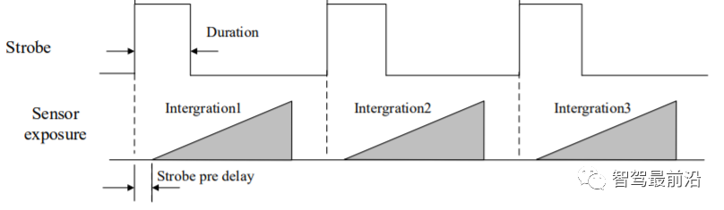
##Strobe signal pre-output timing Now let’s get back to the topic, it’s going to go really fast now.
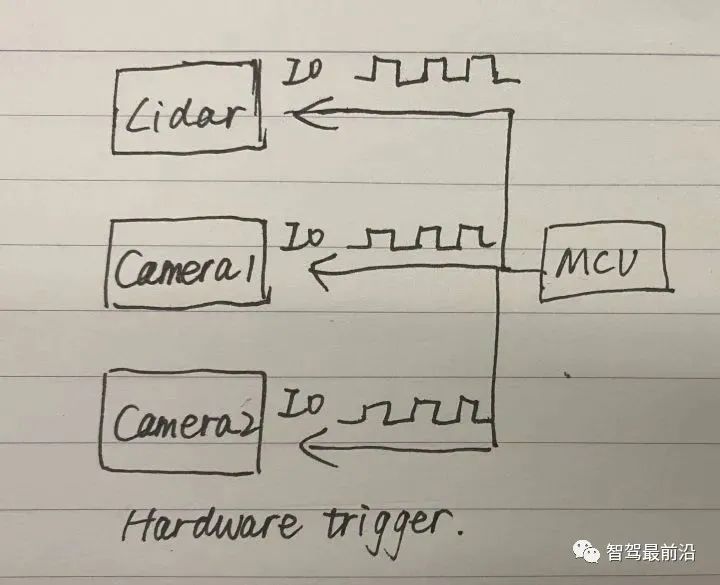
There are three main ways to synchronize camera and lidar timestamps: hard triggering, soft triggering, and soft triggering plus a hard trigger. Below I introduce them one by one in the form of a hand-drawn schematic diagram.
Let’s talk about hard trigger first. An MCU generates pulse signals to hard trigger three sensor devices.
#For soft triggering and hard triggering, you can first use the API of the camera SDK to soft trigger a camera, and then use the external trigger signal of the camera Strobe performs hard triggering on other sensors such as radar and cameras.
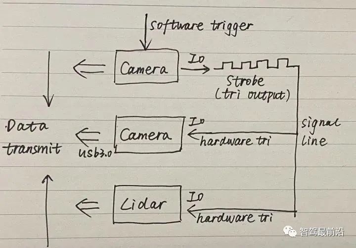
#There is a problem that needs to be noted here. If the first camera that is soft-triggered emits a Strobe signal at the same time as the exposure, the other sensors that are hard-triggered will After all, it is a step too late and cannot be completely synchronized. Therefore, the previously proposed concept of pre-output strobe is introduced, that is, strobe output is performed before delayed exposure.
Pay attention to four points when configuring this mode:
- The triggering method of rising edge or falling edge;
- Effective level width, level amplitude, you want Know the lowest amplitude that can trigger the Lidar;
- Strobe pre-output;
- Whether the level signals on both sides are the same, whether 3v or 5v needs to be boosted;
Finally Let’s talk about soft triggering which is not recommended.
The first call to the API operation is obviously slower than the hard trigger (direct read and write operations on the sensor's internal register). API(1) has already taken some time before executing the second command API(2). time.
<code>//读取lidar和image数据的线程1while(1){API(1); //软触发第一个sensorAPI(2); //软触发第二个sensor//假设脉冲周期为0.5s}//处理数据线程2for(i=0;i<nimage gettickcount t1 gettickfrequency></nimage></code>When the time required to process a single frame of data exceeds 0.5 seconds, thread 1 will read the next frame of data, causing the data of thread 2 to be confused. Thread 2 must complete processing of a single frame within 0.5 seconds and needs to wait after each frame (1/fps - current frame processing time).
The above is the detailed content of An article talks about the time stamp synchronization problem of lidar and camera calibration. For more information, please follow other related articles on the PHP Chinese website!

Hot AI Tools

Undresser.AI Undress
AI-powered app for creating realistic nude photos

AI Clothes Remover
Online AI tool for removing clothes from photos.

Undress AI Tool
Undress images for free

Clothoff.io
AI clothes remover

AI Hentai Generator
Generate AI Hentai for free.

Hot Article
Hot Tools

Notepad++7.3.1
Easy-to-use and free code editor

SublimeText3 Chinese version
Chinese version, very easy to use

Zend Studio 13.0.1
Powerful PHP integrated development environment

Dreamweaver CS6
Visual web development tools

SublimeText3 Mac version
God-level code editing software (SublimeText3)
Hot Topics
 1386
1386
 52
52

 The Stable Diffusion 3 paper is finally released, and the architectural details are revealed. Will it help to reproduce Sora?
Mar 06, 2024 pm 05:34 PM
The Stable Diffusion 3 paper is finally released, and the architectural details are revealed. Will it help to reproduce Sora?
Mar 06, 2024 pm 05:34 PM
StableDiffusion3’s paper is finally here! This model was released two weeks ago and uses the same DiT (DiffusionTransformer) architecture as Sora. It caused quite a stir once it was released. Compared with the previous version, the quality of the images generated by StableDiffusion3 has been significantly improved. It now supports multi-theme prompts, and the text writing effect has also been improved, and garbled characters no longer appear. StabilityAI pointed out that StableDiffusion3 is a series of models with parameter sizes ranging from 800M to 8B. This parameter range means that the model can be run directly on many portable devices, significantly reducing the use of AI
 Have you really mastered coordinate system conversion? Multi-sensor issues that are inseparable from autonomous driving
Oct 12, 2023 am 11:21 AM
Have you really mastered coordinate system conversion? Multi-sensor issues that are inseparable from autonomous driving
Oct 12, 2023 am 11:21 AM
The first pilot and key article mainly introduces several commonly used coordinate systems in autonomous driving technology, and how to complete the correlation and conversion between them, and finally build a unified environment model. The focus here is to understand the conversion from vehicle to camera rigid body (external parameters), camera to image conversion (internal parameters), and image to pixel unit conversion. The conversion from 3D to 2D will have corresponding distortion, translation, etc. Key points: The vehicle coordinate system and the camera body coordinate system need to be rewritten: the plane coordinate system and the pixel coordinate system. Difficulty: image distortion must be considered. Both de-distortion and distortion addition are compensated on the image plane. 2. Introduction There are four vision systems in total. Coordinate system: pixel plane coordinate system (u, v), image coordinate system (x, y), camera coordinate system () and world coordinate system (). There is a relationship between each coordinate system,
 This article is enough for you to read about autonomous driving and trajectory prediction!
Feb 28, 2024 pm 07:20 PM
This article is enough for you to read about autonomous driving and trajectory prediction!
Feb 28, 2024 pm 07:20 PM
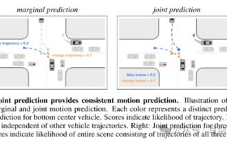
Trajectory prediction plays an important role in autonomous driving. Autonomous driving trajectory prediction refers to predicting the future driving trajectory of the vehicle by analyzing various data during the vehicle's driving process. As the core module of autonomous driving, the quality of trajectory prediction is crucial to downstream planning control. The trajectory prediction task has a rich technology stack and requires familiarity with autonomous driving dynamic/static perception, high-precision maps, lane lines, neural network architecture (CNN&GNN&Transformer) skills, etc. It is very difficult to get started! Many fans hope to get started with trajectory prediction as soon as possible and avoid pitfalls. Today I will take stock of some common problems and introductory learning methods for trajectory prediction! Introductory related knowledge 1. Are the preview papers in order? A: Look at the survey first, p
 DualBEV: significantly surpassing BEVFormer and BEVDet4D, open the book!
Mar 21, 2024 pm 05:21 PM
DualBEV: significantly surpassing BEVFormer and BEVDet4D, open the book!
Mar 21, 2024 pm 05:21 PM
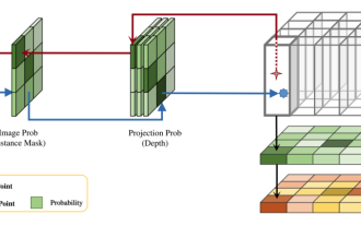
This paper explores the problem of accurately detecting objects from different viewing angles (such as perspective and bird's-eye view) in autonomous driving, especially how to effectively transform features from perspective (PV) to bird's-eye view (BEV) space. Transformation is implemented via the Visual Transformation (VT) module. Existing methods are broadly divided into two strategies: 2D to 3D and 3D to 2D conversion. 2D-to-3D methods improve dense 2D features by predicting depth probabilities, but the inherent uncertainty of depth predictions, especially in distant regions, may introduce inaccuracies. While 3D to 2D methods usually use 3D queries to sample 2D features and learn the attention weights of the correspondence between 3D and 2D features through a Transformer, which increases the computational and deployment time.
 The first multi-view autonomous driving scene video generation world model | DrivingDiffusion: New ideas for BEV data and simulation
Oct 23, 2023 am 11:13 AM
The first multi-view autonomous driving scene video generation world model | DrivingDiffusion: New ideas for BEV data and simulation
Oct 23, 2023 am 11:13 AM
Some of the author’s personal thoughts In the field of autonomous driving, with the development of BEV-based sub-tasks/end-to-end solutions, high-quality multi-view training data and corresponding simulation scene construction have become increasingly important. In response to the pain points of current tasks, "high quality" can be decoupled into three aspects: long-tail scenarios in different dimensions: such as close-range vehicles in obstacle data and precise heading angles during car cutting, as well as lane line data. Scenes such as curves with different curvatures or ramps/mergings/mergings that are difficult to capture. These often rely on large amounts of data collection and complex data mining strategies, which are costly. 3D true value - highly consistent image: Current BEV data acquisition is often affected by errors in sensor installation/calibration, high-precision maps and the reconstruction algorithm itself. this led me to
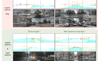
 Easily understand 4K HD images! This large multi-modal model automatically analyzes the content of web posters, making it very convenient for workers.
Apr 23, 2024 am 08:04 AM
Easily understand 4K HD images! This large multi-modal model automatically analyzes the content of web posters, making it very convenient for workers.
Apr 23, 2024 am 08:04 AM
A large model that can automatically analyze the content of PDFs, web pages, posters, and Excel charts is not too convenient for workers. The InternLM-XComposer2-4KHD (abbreviated as IXC2-4KHD) model proposed by Shanghai AILab, the Chinese University of Hong Kong and other research institutions makes this a reality. Compared with other multi-modal large models that have a resolution limit of no more than 1500x1500, this work increases the maximum input image of multi-modal large models to more than 4K (3840x1600) resolution, and supports any aspect ratio and 336 pixels to 4K Dynamic resolution changes. Three days after its release, the model topped the HuggingFace visual question answering model popularity list. Easy to handle
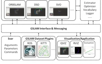 GSLAM | A general SLAM architecture and benchmark
Oct 20, 2023 am 11:37 AM
GSLAM | A general SLAM architecture and benchmark
Oct 20, 2023 am 11:37 AM
Suddenly discovered a 19-year-old paper GSLAM: A General SLAM Framework and Benchmark open source code: https://github.com/zdzhaoyong/GSLAM Go directly to the full text and feel the quality of this work ~ 1 Abstract SLAM technology has achieved many successes recently and attracted many attracted the attention of high-tech companies. However, how to effectively perform benchmarks on speed, robustness, and portability with interfaces to existing or emerging algorithms remains a problem. In this paper, a new SLAM platform called GSLAM is proposed, which not only provides evaluation capabilities but also provides researchers with a useful way to quickly develop their own SLAM systems.
 CVPR 2024 | LiDAR diffusion model for photorealistic scene generation
Apr 24, 2024 pm 04:28 PM
CVPR 2024 | LiDAR diffusion model for photorealistic scene generation
Apr 24, 2024 pm 04:28 PM
Original title: TowardsRealisticSceneGenerationwithLiDARDiffusionModels Paper link: https://hancyran.github.io/assets/paper/lidar_diffusion.pdf Code link: https://lidar-diffusion.github.io Author affiliation: CMU Toyota Research Institute University of Southern California Paper ideas : Diffusion models (DMs) excel at photorealistic image synthesis, but adapting them to lidar scene generation presents significant challenges. This is mainly because DMs operating in point space have difficulty
