

In-depth interpretation of smart car sensor calibration technology

Calibrating sensors is a necessary link in the autonomous driving perception system and a necessary step and prerequisite for subsequent sensor fusion. Its purpose is to transform two or more sensors into a unified spatio-temporal coordinate system so that sensor fusion can be achieved Having meaning is a key prerequisite for perceptual decision-making. Any sensor needs to be calibrated through experiments after manufacturing and installation to ensure that the sensor meets the design specifications and ensures the accuracy of the measurement values.
After the sensor is installed on the autonomous vehicle, it needs to be calibrated; at the same time, during the driving process of the vehicle, due to vibration and other reasons, the sensor position will deviate from the original position. , so it is necessary to calibrate the sensor at certain intervals. Self-driving cars work simultaneously through multiple types of sensors for environmental perception and self-awareness. The robustness and accuracy of sensors are particularly important in the perception process of self-driving cars.
01 Camera calibration
The vehicle-mounted camera is installed on the vehicle at a certain angle and position. In order to compare the environmental data collected by the vehicle-mounted camera with To correspond to real objects in the vehicle driving environment, that is, to find the conversion relationship between the point coordinates in the image pixel coordinate system generated by the vehicle camera and the point coordinates in the camera environment coordinate system, camera calibration is required.
1. Camera internal parameter calibration
1.1 Establishment of camera model
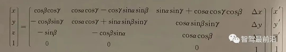
Through the mutual conversion relationship between the environment coordinate system, camera coordinate system, image physical coordinate system, and image pixel coordinate system, we can find the conversion relationship between the environment coordinate system and the image pixel coordinate system, that is,
Point P for the real world. Its coordinates in the environment coordinate system are (Xw, Yw, Zw), and its position in the image is (u, v). The two have the following relationship:
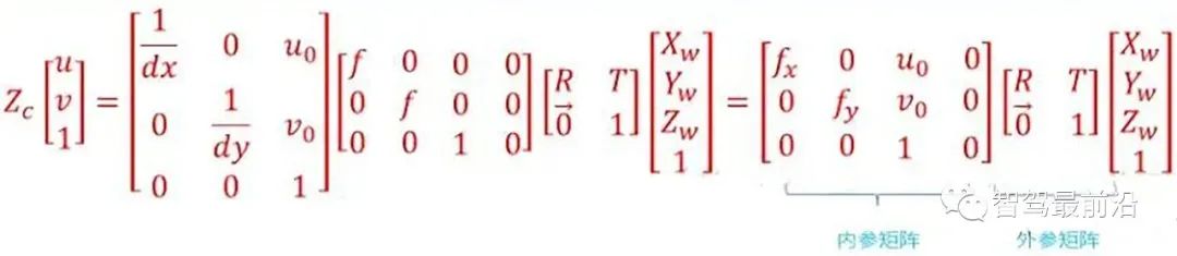
Conversion relationship between the environment coordinate system and the image pixel coordinate system
For the internal parameter matrix, the fourth constants fx, fy, Uo, Vo. It is related to the design technical indicators such as the focal length, main point and sensor of the camera, and has nothing to do with external factors (such as the surrounding environment, camera position), so it is called the internal parameter of the camera. The internal reference is determined when the camera leaves the factory. However, due to manufacturing process and other issues, even cameras produced on the same production line have slightly different internal parameters. Therefore, it is often necessary to determine the internal parameters of the camera through experiments. The calibration of a monocular camera usually refers to determining the internal parameters of the camera through experimental means.
The external parameter matrix includes the rotation matrix and the translation matrix. The rotation matrix and the translation matrix jointly describe how to convert the point from the world coordinate system to the camera coordinate system. In computer vision, the process of determining the external parameter matrix is usually called visual localization. After the on-board camera is installed in a self-driving car, the camera position needs to be calibrated in the vehicle coordinate system. In addition, due to the bumps and vibrations of the car, the position of the on-board camera will slowly change over time, so self-driving cars need to recalibrate the camera position regularly, a process called calibration.
1.2 Camera distortion correction
In actual use, the camera cannot completely accurately follow the ideal pinhole When the camera model performs perspective projection, there is usually lens distortion, that is, there is a certain optical distortion error between the image generated by the object point on the actual camera imaging plane and the ideal imaging. The distortion error is mainly radial distortion error and tangential distortion error. .
Radial distortion: Due to the characteristics of the lens, light tends to bend to a small or large extent at the edge of the camera lens, which is called radial distortion. This kind of distortion is more obvious in ordinary cheap lenses. Radial distortion mainly includes barrel distortion and pincushion distortion. Barrel distortion is a barrel-shaped expansion of the imaging image caused by the structure of the lens object and the lens group in the lens. Barrel distortion is usually easier to detect when using a wide-angle lens or when using the wide-angle end of a zoom lens. Pincushion distortion is the phenomenon of the image "shrinking" toward the center caused by the lens. People are more likely to notice pincushion distortion when using the telephoto end of a zoom lens.
- Tangential distortion: It is caused by the fact that the lens itself is not parallel to the camera sensor plane (imaging plane) or image plane. This situation is mostly caused by the lens being pasted to the lens mold. Caused by installation deviation on the group.
#In computer vision, radial distortion has a very important impact on scene reconstruction. The autonomous driving system's perception of the environment requires the camera to achieve high-precision reconstruction of the surrounding environment. If distortion is not corrected, accurate environmental information cannot be obtained. For example, targets in the environment may appear in any area of the image. If distortion is not corrected, the target location and size obtained through vision technology are often inaccurate, which will directly affect the driving safety of autonomous vehicles. In addition, self-driving cars are equipped with multiple cameras at different locations. If radial distortion is not considered, during the image stitching process, the blur effect of the stitched images will be caused by mismatching of corresponding features.
For general cameras, the radial distortion of the image is often described as a low-order polynomial model. Assume (u, v) is the coordinate of the corrected point, (u', u') is the coordinate of the uncorrected point, then the transformation between the two can be determined by the following formula:
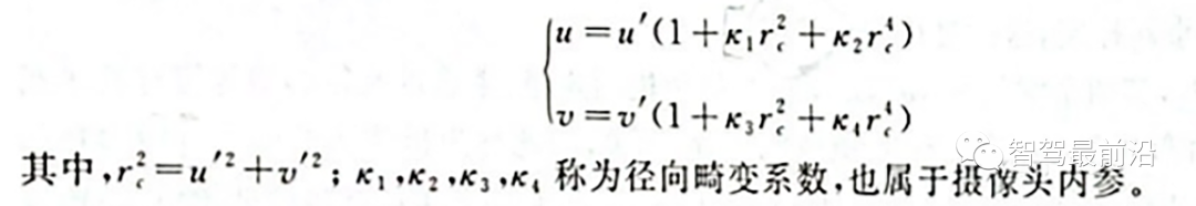
Radial distortion low-order polynomial model
On the other hand, for the cut Tangential distortion can be corrected using the other two parameters p1 and p2:
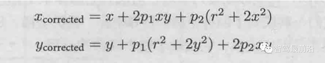
Tangential distortion Low-order polynomial model
##1.3 Camera internal parameter calibration method
##At this stage, the calibration of distortion parameters is generally performed simultaneously with other internal parameters. The most widely used one at present is the Zhang Zhengyou calibration method proposed by Zhang Zhengyou in 2000. Zhang Zhengyou's calibration method finds the internal corner points of the chessboard calibration board in each image by photographing the chessboard calibration board at different positions, and establishes constraints on the matrix through the correspondence between the internal corner points. Thereby restoring the internal parameter matrix K. 
In self-driving cars, in order to minimize the perception blind area, a multi-camera mode is often used . Determining the relative positional relationship between multiple cameras is called the external parameter calibration of the camera.
From another perspective, the external parameter calibration of the camera can also be called the "pose estimation" problem. The relative pose [R|t] between the two cameras has 6 degrees of freedom (spatial position and rotation relationship). Theoretically, as long as the two cameras acquire 3 points in the space at the same time, the relationship between the two can be restored. relative posture. The problem of recovering the relative posture between cameras from three pairs of corresponding points is called the "Perspective-3-Point-Problem, P3P". In reality, more than 3 points are often used to restore the relative posture to improve robustness, and the P3P problem is generalized as a PnP problem.
Initially, researchers used the Direct Linear Transform (DLT) method to solve the PnP problem. Later, in order to improve the accuracy, the researchers proposed a robust linearization reprojection error. The generation selection method is used to solve the PnP problem, and the famous bundle adjustment method (Bundle Adjustment, BA) in attitude estimation is proposed.
02 Lidar calibration
Lidar is one of the main sensors of the autonomous driving platform and plays an important role in perception and positioning. Like cameras, lidar also needs to calibrate its internal and external parameters before use. Internal parameter calibration refers to the conversion relationship between its internal laser transmitter coordinate system and the radar's own coordinate system. It has been calibrated before leaving the factory and can be used directly. What the autonomous driving system needs to perform is external parameter calibration, that is, the relationship between the lidar's own coordinate system and the vehicle body coordinate system.The lidar and the vehicle body are rigidly connected, and the relative posture and displacement between the two are fixed. In order to establish the relative coordinate relationship between lidars and between lidars and vehicles, it is necessary to calibrate the lidar installation and convert the lidar data from the lidar coordinate system to the vehicle body coordinate system. 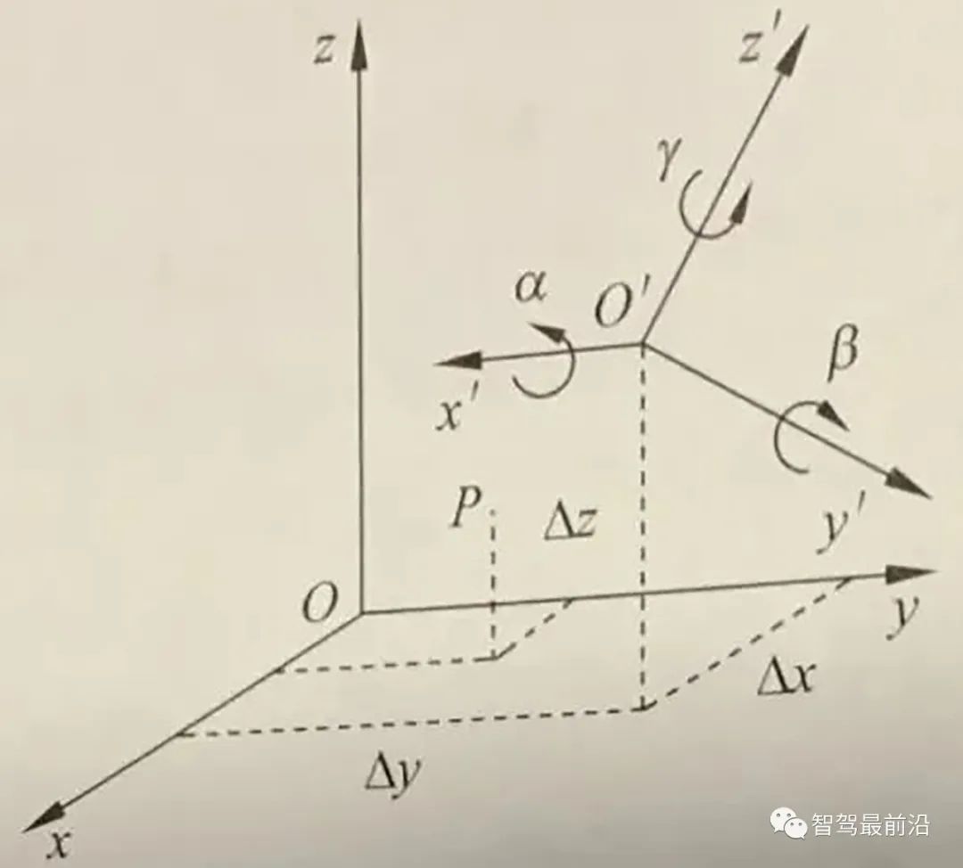
##Car body coordinate system and lidar coordinate system
Through experiments, we collect the real coordinates of the same point in two coordinate systems, that is, the point with the same name, and establish a series of equations to calculate these 16 Unknown parameters. In addition, in autonomous vehicles, it is usually necessary to calibrate the laser radar and the inertial navigation unit (IMU) coordinate system to establish the relationship between the laser radar and the vehicle body coordinate system.
1. Calibration between LiDAR and LiDAR
For autonomous vehicles, sometimes there are multiple LiDARs In this case, each external environment acquired by lidar must be accurately mapped to the vehicle body coordinate system. Therefore, when there are multiple lidars, the relative positions of the multiple lidars need to be calibrated and calibrated.
There are many ideas for calibrating external parameters between lidars. The more commonly used one is to indirectly derive the relationship between lidars through the coordinate conversion relationship between different lidars and the car body. coordinate transformation relationship between them.
2. Calibration of lidar and camera
In an autonomous vehicle, the lidar and the driverless vehicle are rigidly connected. The relative attitude and displacement between them are fixed. Therefore, the data points obtained by lidar scanning have unique position coordinates corresponding to them in the environmental coordinate system. Similarly, the camera also has unique position coordinates in the environment coordinate system, so there is a fixed coordinate transformation between the lidar and the camera. The joint calibration of lidar and cameras is to complete the unification of multiple sensor coordinates such as single-line lidar coordinates, camera coordinates, and image pixel coordinates by extracting the corresponding feature points of the calibration object on the single-line lidar and image, and realize the lidar and camera spatial calibration.
After the camera external parameter calibration and lidar external parameter calibration are completed, the relationship between the two can actually be completely determined. The lidar scanning point can be projected to the image pixel coordinate system.
Same as the internal parameter calibration method of the camera, the external parameter calibration method of the lidar and camera can also use the calibration method of the calibration plate.
The above is the detailed content of In-depth interpretation of smart car sensor calibration technology. For more information, please follow other related articles on the PHP Chinese website!

Hot AI Tools

Undresser.AI Undress
AI-powered app for creating realistic nude photos

AI Clothes Remover
Online AI tool for removing clothes from photos.

Undress AI Tool
Undress images for free

Clothoff.io
AI clothes remover

Video Face Swap
Swap faces in any video effortlessly with our completely free AI face swap tool!

Hot Article
Hot Tools

Notepad++7.3.1
Easy-to-use and free code editor

SublimeText3 Chinese version
Chinese version, very easy to use

Zend Studio 13.0.1
Powerful PHP integrated development environment

Dreamweaver CS6
Visual web development tools

SublimeText3 Mac version
God-level code editing software (SublimeText3)
Hot Topics
 1387
1387
 52
52

 Why is Gaussian Splatting so popular in autonomous driving that NeRF is starting to be abandoned?
Jan 17, 2024 pm 02:57 PM
Why is Gaussian Splatting so popular in autonomous driving that NeRF is starting to be abandoned?
Jan 17, 2024 pm 02:57 PM
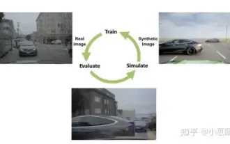
Written above & the author’s personal understanding Three-dimensional Gaussiansplatting (3DGS) is a transformative technology that has emerged in the fields of explicit radiation fields and computer graphics in recent years. This innovative method is characterized by the use of millions of 3D Gaussians, which is very different from the neural radiation field (NeRF) method, which mainly uses an implicit coordinate-based model to map spatial coordinates to pixel values. With its explicit scene representation and differentiable rendering algorithms, 3DGS not only guarantees real-time rendering capabilities, but also introduces an unprecedented level of control and scene editing. This positions 3DGS as a potential game-changer for next-generation 3D reconstruction and representation. To this end, we provide a systematic overview of the latest developments and concerns in the field of 3DGS for the first time.
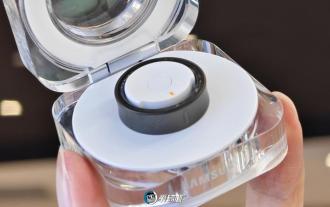 Wow awesome! Samsung Galaxy Ring experience: 2999 yuan real smart ring
Jul 19, 2024 pm 02:31 PM
Wow awesome! Samsung Galaxy Ring experience: 2999 yuan real smart ring
Jul 19, 2024 pm 02:31 PM
Samsung officially released the national version of Samsung Galaxy Ring on July 17, priced at 2,999 yuan. Galaxy Ring's real phone is really the 2024 version of "WowAwesome, this is my exclusive moment". It is the electronic product that makes us feel the freshest in recent years (although it sounds like a flag) besides Apple's Vision Pro. (In the picture, the rings on the left and right are Galaxy Ring↑) Samsung Galaxy Ring specifications (data from the official website of the Bank of China): ZephyrRTOS system, 8MB storage; 10ATM waterproof + IP68; battery capacity 18mAh to 23.5mAh (different sizes
 How to solve the long tail problem in autonomous driving scenarios?
Jun 02, 2024 pm 02:44 PM
How to solve the long tail problem in autonomous driving scenarios?
Jun 02, 2024 pm 02:44 PM
Yesterday during the interview, I was asked whether I had done any long-tail related questions, so I thought I would give a brief summary. The long-tail problem of autonomous driving refers to edge cases in autonomous vehicles, that is, possible scenarios with a low probability of occurrence. The perceived long-tail problem is one of the main reasons currently limiting the operational design domain of single-vehicle intelligent autonomous vehicles. The underlying architecture and most technical issues of autonomous driving have been solved, and the remaining 5% of long-tail problems have gradually become the key to restricting the development of autonomous driving. These problems include a variety of fragmented scenarios, extreme situations, and unpredictable human behavior. The "long tail" of edge scenarios in autonomous driving refers to edge cases in autonomous vehicles (AVs). Edge cases are possible scenarios with a low probability of occurrence. these rare events
 Choose camera or lidar? A recent review on achieving robust 3D object detection
Jan 26, 2024 am 11:18 AM
Choose camera or lidar? A recent review on achieving robust 3D object detection
Jan 26, 2024 am 11:18 AM
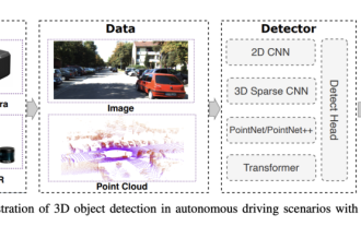
0.Written in front&& Personal understanding that autonomous driving systems rely on advanced perception, decision-making and control technologies, by using various sensors (such as cameras, lidar, radar, etc.) to perceive the surrounding environment, and using algorithms and models for real-time analysis and decision-making. This enables vehicles to recognize road signs, detect and track other vehicles, predict pedestrian behavior, etc., thereby safely operating and adapting to complex traffic environments. This technology is currently attracting widespread attention and is considered an important development area in the future of transportation. one. But what makes autonomous driving difficult is figuring out how to make the car understand what's going on around it. This requires that the three-dimensional object detection algorithm in the autonomous driving system can accurately perceive and describe objects in the surrounding environment, including their locations,
 Upgrade to full screen! iPhone SE4 advanced to September
Jul 24, 2024 pm 12:56 PM
Upgrade to full screen! iPhone SE4 advanced to September
Jul 24, 2024 pm 12:56 PM
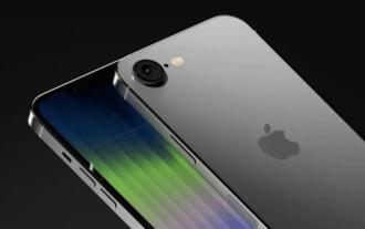
Recently, new news about iPhone SE4 was revealed on Weibo. It is said that the back cover process of iPhone SE4 is exactly the same as that of the iPhone 16 standard version. In other words, iPhone SE4 will use a glass back panel and a straight screen and straight edge design. It is reported that iPhone SE4 will be released in advance to September this year, which means it is likely to be unveiled at the same time as iPhone 16. 1. According to the exposed renderings, the front design of iPhone SE4 is similar to that of iPhone 13, with a front camera and FaceID sensor on the notch screen. The back uses a layout similar to the iPhoneXr, but it only has one camera and does not have an overall camera module.
 How big is the 1-inch sensor of a mobile phone? It's actually bigger than the 1-inch sensor of a camera
May 08, 2024 pm 06:40 PM
How big is the 1-inch sensor of a mobile phone? It's actually bigger than the 1-inch sensor of a camera
May 08, 2024 pm 06:40 PM
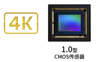
Yesterday's article didn't mention "sensor size". I didn't expect people to have so many misunderstandings... How much is 1 inch? Because of some historical issues*, whether it is a camera or a mobile phone, "1 inch" in the diagonal length of the sensor is not 25.4mm. *When it comes to vacuum tubes, there is no expansion here. It is a bit like a horse’s butt deciding the width of a railroad track. In order to avoid misunderstanding, the more rigorous writing is "Type 1.0" or "Type1.0". Moreover, when the sensor size is less than 1/2 type, type 1 = 18mm; and when the sensor size is greater than or equal to 1/2 type, type 1 =
 This article is enough for you to read about autonomous driving and trajectory prediction!
Feb 28, 2024 pm 07:20 PM
This article is enough for you to read about autonomous driving and trajectory prediction!
Feb 28, 2024 pm 07:20 PM
Trajectory prediction plays an important role in autonomous driving. Autonomous driving trajectory prediction refers to predicting the future driving trajectory of the vehicle by analyzing various data during the vehicle's driving process. As the core module of autonomous driving, the quality of trajectory prediction is crucial to downstream planning control. The trajectory prediction task has a rich technology stack and requires familiarity with autonomous driving dynamic/static perception, high-precision maps, lane lines, neural network architecture (CNN&GNN&Transformer) skills, etc. It is very difficult to get started! Many fans hope to get started with trajectory prediction as soon as possible and avoid pitfalls. Today I will take stock of some common problems and introductory learning methods for trajectory prediction! Introductory related knowledge 1. Are the preview papers in order? A: Look at the survey first, p
 Let's talk about end-to-end and next-generation autonomous driving systems, as well as some misunderstandings about end-to-end autonomous driving?
Apr 15, 2024 pm 04:13 PM
Let's talk about end-to-end and next-generation autonomous driving systems, as well as some misunderstandings about end-to-end autonomous driving?
Apr 15, 2024 pm 04:13 PM
In the past month, due to some well-known reasons, I have had very intensive exchanges with various teachers and classmates in the industry. An inevitable topic in the exchange is naturally end-to-end and the popular Tesla FSDV12. I would like to take this opportunity to sort out some of my thoughts and opinions at this moment for your reference and discussion. How to define an end-to-end autonomous driving system, and what problems should be expected to be solved end-to-end? According to the most traditional definition, an end-to-end system refers to a system that inputs raw information from sensors and directly outputs variables of concern to the task. For example, in image recognition, CNN can be called end-to-end compared to the traditional feature extractor + classifier method. In autonomous driving tasks, input data from various sensors (camera/LiDAR
