 Operation and Maintenance
 Safety
 What is the hardware architecture in industrial firewall architecture and technology?
What is the hardware architecture in industrial firewall architecture and technology?
1)、Meet the stability requirements of the industrial environment
From the perspective of meeting the stability requirements of the industrial environment, the need for industrial firewalls should be considered from the hardware and software levels. Consider the impact of its own stability on industrial networks. From this perspective, industrial firewalls need to have both software and hardware bypass functions. If an industrial firewall fails, you don't have to worry about the industrial network being disconnected, because the Bypass function will automatically start to ensure normal operation of the network. Bypass, as the name suggests, is a bypass protection system, which means that two networks can be physically connected directly without passing through the industrial firewall system through a specific triggering state (power outage or crash). At this time, the industrial firewall will no longer process the data packets in the network. Based on this design, Bypass is itself a vulnerability from the perspective of security attacks. As long as the attacker finds a way to make the industrial firewall trigger the Bypass function, then the industrial firewall that triggers the Bypass function will be safely isolated and The control function loses its effect, and the attacker can directly access internal protected resources. So is this idea feasible? Is there such a vulnerability in the Bypass function? Let's take a look at how the Bypass function is designed and implemented.
Here I use the simplest model to explain the architecture and working principle of Bypass. In an industrial firewall, if the design of the Bypass function is based on the industrial Ethernet environment, then it is related to the industrial motherboard and network card. This Bypass function varies depending on the design architecture of the motherboard and network card.
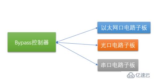
From the simplest ByPass model, this model contains two parts: "bypass controller" and "execution circuit board". The bypass controller is the control and scheduling core of the entire system, and the execution circuit sub-board is the specific executor. This executor acts on different network transmission media (such as electrical ports, optical ports, serial ports, etc.). As shown in the figure below:
#How does this executor act on different network transmission media? This requires us to understand the components and their relationships between the underlying network transmission media. We use the architecture of the network card as an illustration of this transmission medium.
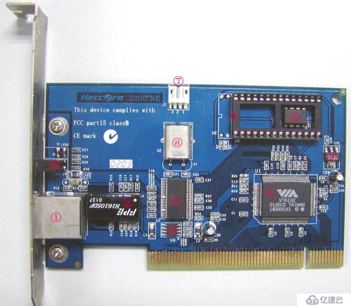
This is a physical picture of the network card, which contains all the components of the network card:
①RJ-45 interface
②Transformer( Isolation transformer)
③PHY chip
④MAC chip
⑤EEPROM
⑥BOOTROM slot
⑦WOL connector
⑧ Crystal oscillator
⑨Voltage conversion chip
⑩LED indicator
You can see many components and equipment that we didn’t know much about before. The following is a brief introduction to the functions of each component.
RJ-45 is a socket module. Simply put, it is a transmitter or receiver. RJ-45 has 8 pins. When the network card generally uses an RJ-45 socket, the RJ-45 socket of the 10M network card only uses four pins 1, 2, 3, and 6, while the 100M or 1000M network card uses all eight pins. are all used. Each of its pins is responsible for sending and receiving data and is not used for other purposes. It mainly exists at both ends of the network cable and on various network Ethernet devices. It is just a socket without any logic control intelligence in it, so what it connects backward is the PHY chip.
PHY is a physical interface transceiver and a component used by the network card to implement the physical layer. The IEEE-802.3 standard defines the Ethernet PHY, including MII/GMII (Media Independent Interface) sublayer, PCS (Physical Coding Sublayer), PMA (Physical Medium Attachment) sublayer, PMD (Physical Medium Dependent) sublayer, MDI sublayer layer. Its interior is also a precision component with a very complex structure. When the PHY sends data, it receives the data from the MAC (for the PHY, there is no concept of a frame. To it, it is all data regardless of the address, the data is still CRC. For 100BaseTX, because 4B/5B encoding is used, Add 1 bit of error detection code for every 4 bits), then convert the parallel data into serial stream data, then encode the data according to the encoding rules of the physical layer, and then turn it into an analog signal to send the data out. The process when receiving the data is reversed. Another important function of PHY is to implement some functions of CSMA/CD. It can detect whether there is data being transmitted on the network. If there is data being transmitted, it will wait. Once it detects that the network is idle, it will wait for a random time before sending the data out. If the two happen to send data at the same time, it will definitely cause a conflict. At this time, the conflict detection mechanism can detect the conflict, and then each waits for a random time to resend the data. This random time is very particular. It is not a constant. The random time calculated at different times is different, and there are multiple algorithms to deal with the second conflict between the same two hosts with a very low probability of occurrence.
The more important thing is that RJ45 and PHY are not together. In other words, the RJ45 on the head of the network cable we usually see does not include a PHY chip. Therefore, in the design of the motherboard, there is a transmission distance between RJ45 and PHY. This is the key to designing Bypass.
The function of the isolation transformer is to filter the differential signal sent out by the PHY with differential mode coupling coil coupling to enhance the signal, and couple it to the other end of the connecting network cable through electromagnetic field conversion. This not only allows the signal to be transmitted without a physical connection between the network cable and the PHY, but also cuts off the DC component in the signal. It can also transmit data in devices with different 0V levels. The isolation transformer is designed for 2KV~3KV voltage and also has lightning induction protection function. Some friends' network equipment is easily burned out during thunderstorms. Most of them are caused by unreasonable PCB design, and most of the interfaces of the equipment are burned out. Few chips are burned out because the isolation transformer plays a role in protecting the chip.
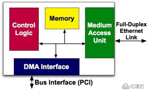
The MAC chip is called a media access controller, which is a chip controller used to implement MAC, or Media Access Control, a media access control sublayer protocol. This protocol is located in the lower half of the data link layer of the OSI seven-layer protocol and is mainly responsible for controlling and connecting the physical media of the physical layer. This layer protocol is the Ethernet MAC defined by the IEEE-802.3 Ethernet standard. The Ethernet data link layer actually includes the MAC (Media Access Control) sublayer and LLC (Logical Link Control) sublayer. The role of an Ethernet card MAC chip is not only to realize the functions of the MAC sublayer and LLC sublayer, but also to provide a PCI or PCIE interface that meets the specifications to realize data exchange with the host. As shown in the figure below:
#The PHY and MAC chips are connected through the MII bus to achieve communication. The subsequent network card component has nothing to do with our implementation of the Bypass function. Current network cards have implemented the PHY chip and MAC chip on the same chip. In other words, the chip connected to the Ethernet interface on the motherboard may be a network controller with both PHY chip and MAC chip functions. After understanding the above concepts, we can explore how Bypass utilizes the transmission path between the PHY and the Ethernet interface.
Insert an Ethernet port circuit daughter board in the middle of the picture, and then connect the daughter board to the Bypass controller to receive the control signal of the switch.
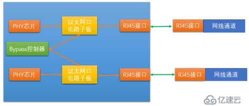
The Ethernet port circuit daughter board contains two components: a relay (electronic switch) and a transformer.
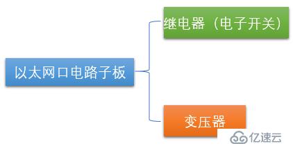
So the more detailed architecture is the structure shown in the figure below:
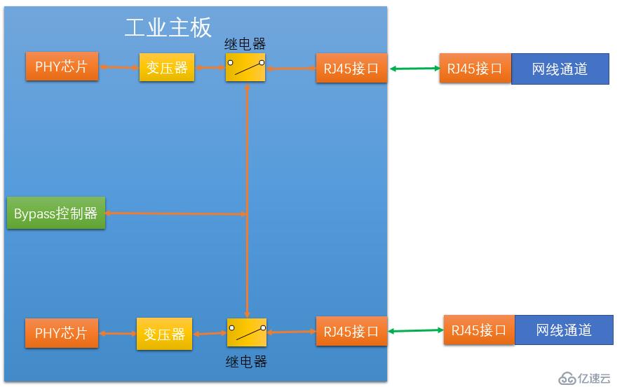
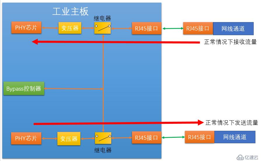
We can see that in There is a transformer and a relay between each PHY chip and the Ethernet interface. These two devices are the specific executors of Bypass. Among them, the relay can be just a simple electronic circuit switch controller, such as an electronic switch. The bypass controller provides control signals to the relays, and the two relays are controlled by the control signals via the control circuit. When our industrial firewall is working normally, the software makes the control signal valid, and the switches of the two relays are in a normal state, that is, the valve of the switch is closed upward, that is, the connection between the transformer and the RJ45 (Ethernet interface) is achieved.
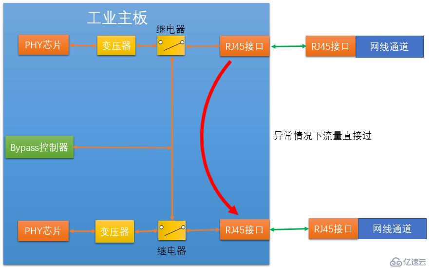
When our industrial firewall fails or loses power, the switches of the two relays jump to the switch connecting the two relays, making the RJ45 and industrial The firewall is disconnected, but the two relays are connected, so that the two RJ45s are connected. This allows the internal and external network interfaces on the industrial firewall to be physically directly connected.
After understanding the lower-level operation method, let’s look at how Bypass triggers. The current Bypass triggering method is to issue control instructions through the Bypass controller. Implement the Bypass function. The Bypass controller receives the following three situations and issues control instructions:
(1) Triggered by power supply. In this way, the Bypass function is usually turned on when the device is not powered on. Once the device is powered on, Bypass is immediately adjusted to normal working status.
(2) is controlled by GPIO (General Purpose Input/Output Port). After entering the operating system, you can operate specific ports through GPIO to control the Bypass switch.
(3) Controlled by Watchdog. This situation is actually an extension of method 2. Watchdog can be used to control the enabling and closing of the GPIO Bypass program, thereby controlling the Bypass status. Using this method, Watchdog can turn on Bypass when the system goes down.
Currently, the implementation of the Bypass function generally implements the first and second types on the device at the same time, and sometimes the three types are also implemented on the same device at the same time. If the device is not powered on, in order to implement the Bypass function, the network card and relay need to be powered at the same time.
Based on this, bypass-enabled Ethernet, fieldbus and 485 bus (if any) all need to have additional power supplies isolated from the main power supply.
The above is the detailed content of What is the hardware architecture in industrial firewall architecture and technology?. For more information, please follow other related articles on the PHP Chinese website!

Hot AI Tools

Undresser.AI Undress
AI-powered app for creating realistic nude photos

AI Clothes Remover
Online AI tool for removing clothes from photos.

Undress AI Tool
Undress images for free

Clothoff.io
AI clothes remover

Video Face Swap
Swap faces in any video effortlessly with our completely free AI face swap tool!

Hot Article

Hot Tools

Notepad++7.3.1
Easy-to-use and free code editor

SublimeText3 Chinese version
Chinese version, very easy to use

Zend Studio 13.0.1
Powerful PHP integrated development environment

Dreamweaver CS6
Visual web development tools

SublimeText3 Mac version
God-level code editing software (SublimeText3)

Hot Topics
 1386
1386
 52
52
 Fix: Windows Activation Error 0x87e10bc6 on Windows 11
Apr 19, 2023 pm 01:37 PM
The Windows 11 activation error 0x87e10bc6 issue occurs when some users try to activate the platform using a product key through settings. When this issue occurs, the Activation tab in Settings displays the following error message: Something is preventing us from communicating with the activation server. Wait a few minutes and try again. Error code: 0x87e10bc6. Specific activation errors may occur because a firewall blocks the connection to Microsoft's activation servers. Therefore, when this error occurs, users cannot activate Windows 11 using their product key. Unfortunately, even Windows 10 users have been plagued by the same issue in the past, so prepare for the benefits
 How to fix 'Error: 0x80070185, Cloud operation was unsuccessful” in OneDrive
May 16, 2023 pm 04:26 PM
OneDrive is a popular cloud storage application provided by Microsoft. Most of us use OneDrive to store our files, folders, documents, etc. But some users complained that when they try to access shared files on OneDrive, it gives an error stating “Error: 0x80070185, Cloud operation was unsuccessful”. Therefore, they cannot perform any operations on OneDrive such as copying files, pasting, downloading shared files, etc. Nowadays, it is necessary to use these operations in our daily work. This error can be easily solved and for this we have some methods that we can apply and try to solve the problem. let's start! Method 1 – Sign out and sign back in to OneDrive app steps
 8 Big Fixes if Grammarly Not Working on Windows 10 Browser
May 05, 2023 pm 02:16 PM
If you have syntax issues on your Windows 10 or 11 PC, this article will help you solve the problem. Grammarly is one of the most popular typing assistants for fixing grammar, spelling, clarity, and more. It has become an essential part of writing professionals. However, if it doesn't work properly, it can be a very frustrating experience. Many Windows users have reported that this tool does not work well on their computers. We did an in-depth analysis and found the cause and solution of this problem. Why doesn't Grammarly work on my PC? Grammarly on PC may not work properly due to several common reasons. It includes the following
 Win11 firewall advanced settings gray solution
Dec 24, 2023 pm 07:53 PM
When setting up the firewall, many friends found that their win11 firewall advanced settings were grayed out and unable to be clicked. This may be caused by not adding a control unit, or by not opening the advanced settings in the correct way. Let’s take a look at how to solve it. Win11 firewall advanced settings gray method one: 1. First, click the start menu below, search and open "Control Panel" at the top 2. Then open "Windows Defender Firewall" 3. After entering, you can open "Advanced Settings" in the left column . Method 2: 1. If the above method cannot be opened, you can right-click "Start Menu" and open "Run" 2. Then enter "mmc" and press Enter to confirm opening. 3. After opening, click on the upper left
 How to Fix Steam Error Code 130 on Windows PC
Apr 28, 2023 pm 01:40 PM
Steam is a popular online game streaming platform that allows its users to purchase and play games as well as chat with other gamers on the platform. In addition to the features it offers, there are also some bugs encountered on the platform. One such error encountered by many Steam users is “Error code: 130 The webpage cannot be loaded (Unknown error)”. This error occurs when the Steam client attempts to load a web page but is unable to retrieve the page from its server. This error code may appear on any page in the Steam client, including inventory pages, update news, or store pages that prevent you from searching for a game you're interested in purchasing. One of the main reasons for this problem is a weak internet connection on your PC. Other possible causes are Stea
 Fix: Windows 11 Firewall blocks printer
May 01, 2023 pm 08:28 PM
Firewalls monitor network traffic and can block network connections for certain programs and hardware. Windows 11 includes its own Windows Defender Firewall, which may block printers from accessing the web. Therefore, affected users cannot use their Brother printers when the firewall blocks it. Keep in mind that this issue affects other brands as well, but today we’ll show you how to fix it. Why is my Brother printer blocked by the firewall? There are several causes for this issue, and you will most likely need to open certain ports before your printer can access the network. Printer software can also cause problems, so be sure to update it as well as your printer driver. Read on to learn how
 How to enable or disable firewall on Alpine Linux?
Feb 21, 2024 pm 12:45 PM
On AlpineLinux, you can use the iptables tool to configure and manage firewall rules. Here are the basic steps to enable or disable the firewall on AlpineLinux: Check the firewall status: sudoiptables -L If the output shows rules (for example, there are some INPUT, OUTPUT, or FORWARD rules), the firewall is enabled. If the output is empty, the firewall is currently disabled. Enable firewall: sudoiptables-PINPUTACCEPTsudoiptables-POUTPUTACCEPTsudoiptables-PFORWARDAC
 Resolve error code 0xc004f074 when activating Windows 11.
May 08, 2023 pm 07:10 PM
After installing the latest operating system on your PC, activating your copy of Windows 11 is the main job. Not only does it unlock the true potential of the Windows 11 operating system, but it also gets rid of the annoying "Activate your Windows 11" message. However, for some users, Windows 11 activation error 0xc004f074 hinders the smooth progress of activation. This bug apparently prevents users from activating Windows 11 and forces them to use an operating system with limited functionality. Windows 11 activation error code 0xc004f074 is related to the Key Management Service. You will encounter this problem when KMS is unavailable. Okay, that's it for this tutorial


