
 Technology peripherals
AI
Have you really mastered coordinate system conversion? Multi-sensor issues that are inseparable from autonomous driving
Technology peripherals
AI
Have you really mastered coordinate system conversion? Multi-sensor issues that are inseparable from autonomous driving
Have you really mastered coordinate system conversion? Multi-sensor issues that are inseparable from autonomous driving


First Introduction and Key Points
This article mainly introduces several commonly used coordinate systems in autonomous driving technology, and how they Complete the association and transformation, and finally build a unified environment model. The focus here is to understand the conversion from vehicle to camera rigid body (external parameters), camera to image conversion (internal parameters), and image to pixel unit conversion. The conversion from 3D to 2D will have corresponding distortion, translation, etc.
Key points: Self-vehicle coordinate systemCamera body coordinate systemWhat needs to be rewritten is: Plane coordinate systemPixel coordinate system Difficulty: Required Considering image distortion, distortion removal and distortion are compensated on the image plane
II Introduction
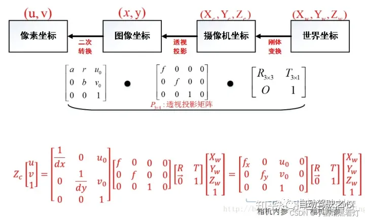
The visual system has a total of four coordinate systems: pixel plane coordinate system ( u,v), image coordinate system (x,y), camera coordinate system () and world coordinate system (). There is a connection between each coordinate system, so how to locate the coordinates of the world coordinate system through the image pixel coordinates needs to be solved through camera calibration. The key algorithm part lies in the coordinate system conversion, and the transformation needs to be completed through the representation of homogeneous coordinates.
Three sensor coordinate systems3.1 Camera coordinate system
The function of the camera is to
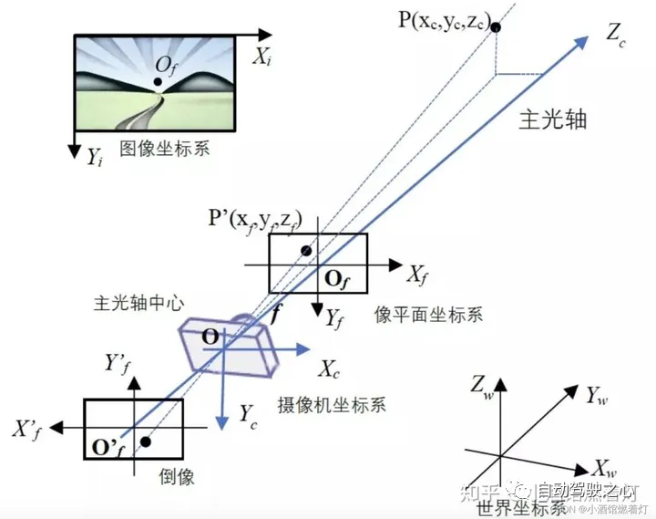
The shape and color information are compressed into a two-dimensional image. The camera-based perception algorithm extracts and restores elements and information in the three-dimensional world from two-dimensional images, such as lane lines, vehicles, pedestrians, etc., and calculates their relative positions to themselves. The coordinate systems related to the perception algorithm and the camera include the image coordinate system (pixel coordinate system) and the camera coordinate system. What needs to be rewritten is: the plane coordinate system
3.1.1 Image coordinate system (or pixel coordinate system) For photos or images stored on the computer, the upper left corner is generally the origin, with the positive x direction to the right and y downward. In the positive direction, the most commonly used unit is "pixel". The image coordinate system is a two-dimensional coordinate system, labeled (Xv, Yv).
The content that needs to be rewritten is: 3.1.2 Camera coordinate systemBecause the x-axis of the image coordinate system is to the right and the y-axis is to the right , so the camera coordinate system takes the center of the main optical axis of the lens as its origin. Generally speaking, the positive direction is the x-axis to the right, the positive direction is the y-axis downward, and the positive direction is the z-axis forward. In this way, the x and y directions are consistent with the direction of the image coordinate system, and the z direction represents the depth of field. The camera coordinate system can be expressed as (Xc, Yc)
What needs to be rewritten is: 3.1.3 What needs to be rewritten is: plane coordinate system (or imaging coordinate system)In order to
quantitatively describe the mapping relationship between three-dimensional space and two-dimensional image, what needs to be rewritten is introduced in graphics: the plane coordinate system. It is a translation of the camera coordinate system. The center is still on the main optical axis of the camera. The distance from the center of the optical axis is equal to the focal length of the camera We know that the camera will be behind the center of the optical axis A reduced inverted image appears on the film, which is the real image plane (Xf, Yf). However, for the convenience of analysis and calculation, we will set up a virtual image plane in front of the center of the optical axis. The image on the virtual image plane is an upright image, and the size is the same as the real inverted image
 What needs to be rewritten is: the plane coordinate system
Depending on the specific situation, any object can be represented, which is introduced by the camera. The unit is meters
 world coordinate system
, camera coordinate system , imaging coordinate system and pixel coordinates System
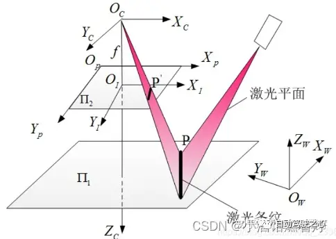
Four Lidar coordinate systemLidar (Light Detection and Ranging) is a
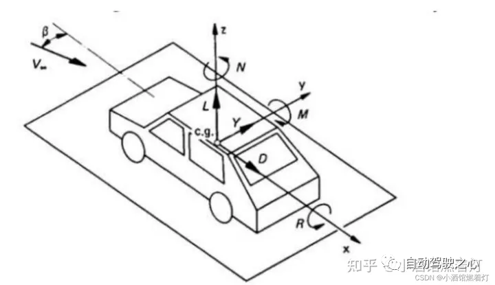
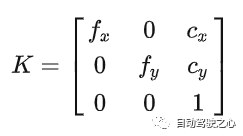
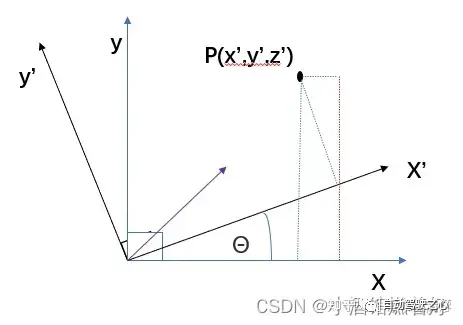
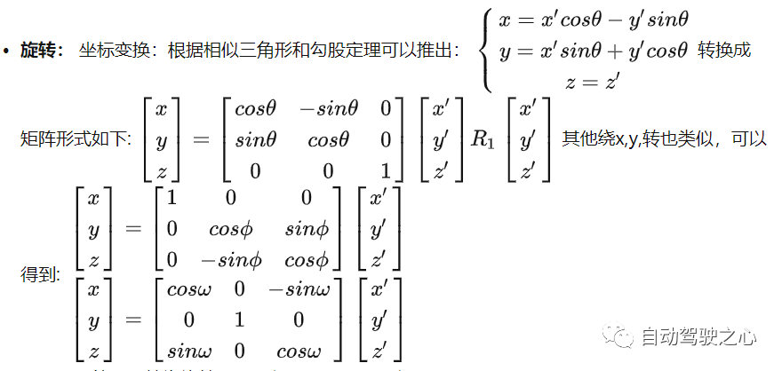
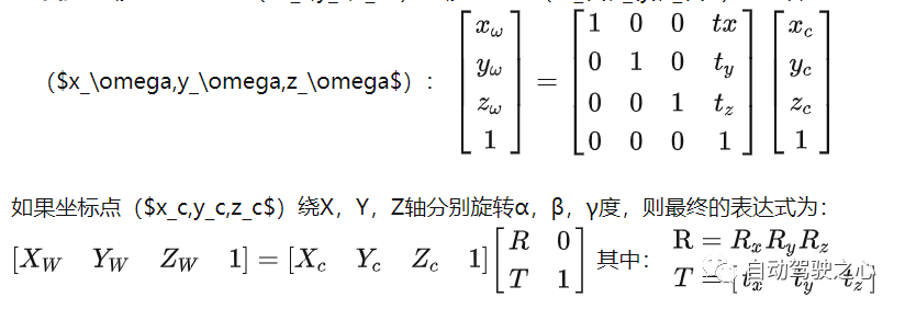
remote sensing technology that uses laser beams to measure objects distance. It emits rays with 360-degree rotation, and forms electric clouds based on different reflections of different target reflectivities. In the fields of autonomous driving and robotics, Lidar is often used as a main sensor to obtain 3D information about the surrounding environment. In most cases, the Lidar coordinate system is right-handed, but the specific definition may vary depending on the Lidar manufacturer. X axis: usually points in front of the Lidar. When the laser beam is fired directly forward, the distance measurement from that direction produces a positive value on the X-axis. Y axis: Usually points to the left side of the Lidar. When the laser beam is fired directly to the left, the distance measurement from that direction produces a positive value on the Y-axis. Z axis: Usually points above the Lidar, perpendicular to the X and Y axes. Height measurements are usually taken along the Z-axis, with positive values representing the object being higher than the Lidar device, and negative values representing it being lower than the Lidar device. describe the position of the sensor and object, this coordinate The system is called the world coordinate system; the self-car coordinate system generally refers to the center of the rear axle of the car body as the origin (because the center of the rear axle will not change relative to the swing of the car) , left front up or right front In the spatial coordinate system on the top, left (right) is generally horizontal, front is generally vertical, and top refers to the space above the ground. The coordinate system moves with the movement of the car. All downstream targets that need to be sensed and output must be under the own vehicle coordinate system, and the BEV perspective target also refers to under this coordinate system position of the object, and uses the rotation angle around these three orthogonal axes (roll angle, pitch angle, yaw angle) represents the attitude of the object. The time coordinate system has only one dimension. For convenience of expression, we generally discuss space coordinates and time coordinates separately. camera main point, camera focal length, and distortion coefficient . Internal parameters are generally given by the merchant, and camera calibration can also be performed. In autonomous driving applications, the internal parameters of the camera are constants and will not change during use, but they need to be calibrated before use. The shooting process of the camera can be abstracted into the process of mapping from the three-dimensional camera coordinate system to the two-dimensional coordinate system: the plane coordinate system, and then mapping to the image coordinate system. Generally, the internal parameters of the camera can be represented by a matrix: This matrix is usually called the internal parameter matrix or camera matrix. Infer the position of the object in the three-dimensional camera coordinate system through the two-dimensional image, such as obtaining distance and depth information. Obtain three-dimensional distance information from a two-dimensional image. If need to obtain the position of the object in the world coordinate system, you also need to know the pose of the camera in the world coordinate system. . This pose representation is called the external parameter of the camera, referred to as the external parameter, and is used to determine the relative positional relationship between the camera coordinates and the world coordinate system. In autonomous driving applications, obtaining this positional relationship requires a series of calibration and positioning work. The camera rotates and translates the matrix relative to other coordinate systems. The rotation external parameter is the Euler angle [yaw, patch, roll] mentioned above. The rotation order is generally (z-y-x), unit degree; the translation external parameter is the translation distance from the camera to the target coordinate system. , unit meter Relationship and conversion: - Since the vehicle moves in the world, the relationship between the self-vehicle coordinate system and the world coordinate system is time changing. - In order to convert between these two coordinate systems, a transformation matrix or transformation (usually consisting of a rotation and a translation) is usually required. This conversion can be obtained through various sensors (such as GPS, IMU, lidar) and algorithms (such as SLAM). - The transformation can be expressed as a 4x4 homogeneous coordinate matrix, allowing us to transform from one coordinate system to another. In most cases, the self-vehicle coordinate system and the world coordinate system are the same, and this is how this article understands The coordinate system transformation between objects can represent the rotation transformation addition of the coordinate system Up translation transformation, the conversion relationship from the world coordinate system to the camera coordinate system is also the same. Rotating different angles around different axes results in different rotation matrices. Schematic diagram of rotating θ around the Z axis: 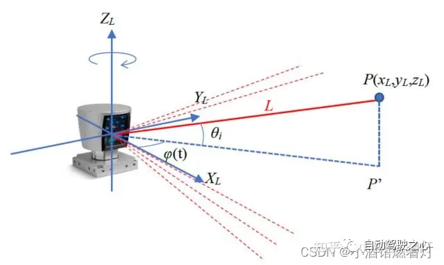
4.1 Definition
4.2 Importance
Five self-vehicle coordinate system
Choose a reference coordinate system in the general environment to 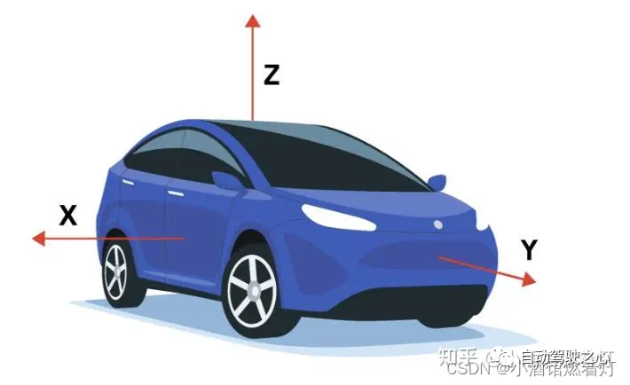
Intrinsic and extrinsic parameters of the six cameras
6.1 Internal parameters of the camera
Internal parameters are used to determine the transformation of the camera from three-dimensional space to two-dimensional space. Projection relationship of dimensional images. It mainly contains three parameters, 6.2 Focal length (f)
It describes the distance between the image
6.3 Principal point
It is a point in the image, usually close to the center of the image. It is the 2D point corresponding to a point in 3D space when projected onto the image plane.
6.4 Distortion coefficient
The lens of a real camera may introduce distortion, causing image distortion. Common distortions include radial distortion and tangential distortion.
 #
#6.5 Camera external parameters
Seven vehicle coordinate system and world coordinate system
7.1 Vehicle Coordinate System
7.2 World Coordinate System
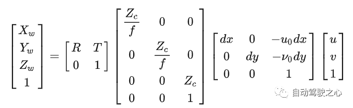
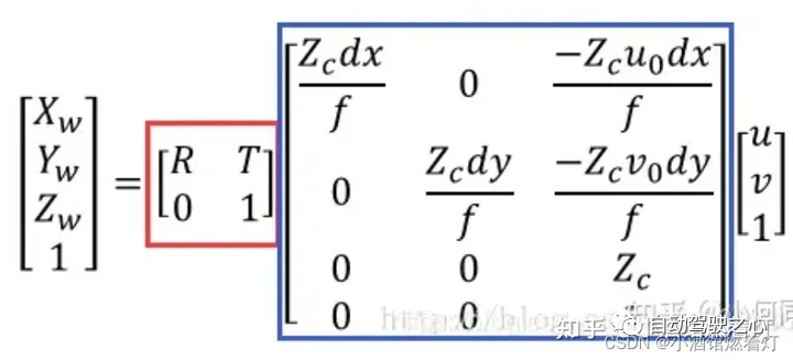
Conversion between eight coordinate systems Relationship
8.1 From the world coordinate system to the camera coordinate system
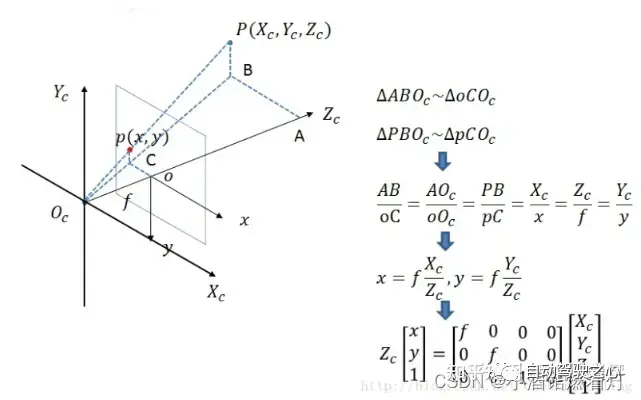
8.2 Camera coordinate system to image coordinate system
From the camera coordinate system to the image coordinate system, it belongs to the perspective projection relationship, converting from 3D to 2D. It can also be viewed as a change model of the pinhole model. Satisfy the triangle similarity theorem.
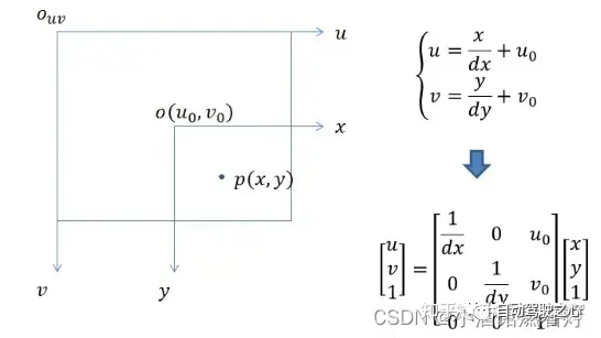
8.3 Image coordinate system to pixel coordinate system
In this case, unlike the previous coordinate system transformation, this There is no rotation transformation, but the position and size of the coordinate origin are inconsistent, so it is necessary to design telescopic transformation and translation transformation
8.4 The relationship between the four coordinate systems
Nine Summary
It sorted out the various coordinate systems of autonomous driving and showed the differences between the various coordinate systems of autonomous driving. relationship, and finally obtain the conversion relationship between the pixel coordinate system and the world coordinate system.

The above is the detailed content of Have you really mastered coordinate system conversion? Multi-sensor issues that are inseparable from autonomous driving. For more information, please follow other related articles on the PHP Chinese website!

Hot AI Tools

Undresser.AI Undress
AI-powered app for creating realistic nude photos

AI Clothes Remover
Online AI tool for removing clothes from photos.

Undress AI Tool
Undress images for free

Clothoff.io
AI clothes remover

AI Hentai Generator
Generate AI Hentai for free.

Hot Article
Hot Tools

Notepad++7.3.1
Easy-to-use and free code editor

SublimeText3 Chinese version
Chinese version, very easy to use

Zend Studio 13.0.1
Powerful PHP integrated development environment

Dreamweaver CS6
Visual web development tools

SublimeText3 Mac version
God-level code editing software (SublimeText3)
Hot Topics
 1377
1377
 52
52

 Why is Gaussian Splatting so popular in autonomous driving that NeRF is starting to be abandoned?
Jan 17, 2024 pm 02:57 PM
Why is Gaussian Splatting so popular in autonomous driving that NeRF is starting to be abandoned?
Jan 17, 2024 pm 02:57 PM
Written above & the author’s personal understanding Three-dimensional Gaussiansplatting (3DGS) is a transformative technology that has emerged in the fields of explicit radiation fields and computer graphics in recent years. This innovative method is characterized by the use of millions of 3D Gaussians, which is very different from the neural radiation field (NeRF) method, which mainly uses an implicit coordinate-based model to map spatial coordinates to pixel values. With its explicit scene representation and differentiable rendering algorithms, 3DGS not only guarantees real-time rendering capabilities, but also introduces an unprecedented level of control and scene editing. This positions 3DGS as a potential game-changer for next-generation 3D reconstruction and representation. To this end, we provide a systematic overview of the latest developments and concerns in the field of 3DGS for the first time.
 How to solve the long tail problem in autonomous driving scenarios?
Jun 02, 2024 pm 02:44 PM
How to solve the long tail problem in autonomous driving scenarios?
Jun 02, 2024 pm 02:44 PM
Yesterday during the interview, I was asked whether I had done any long-tail related questions, so I thought I would give a brief summary. The long-tail problem of autonomous driving refers to edge cases in autonomous vehicles, that is, possible scenarios with a low probability of occurrence. The perceived long-tail problem is one of the main reasons currently limiting the operational design domain of single-vehicle intelligent autonomous vehicles. The underlying architecture and most technical issues of autonomous driving have been solved, and the remaining 5% of long-tail problems have gradually become the key to restricting the development of autonomous driving. These problems include a variety of fragmented scenarios, extreme situations, and unpredictable human behavior. The "long tail" of edge scenarios in autonomous driving refers to edge cases in autonomous vehicles (AVs). Edge cases are possible scenarios with a low probability of occurrence. these rare events
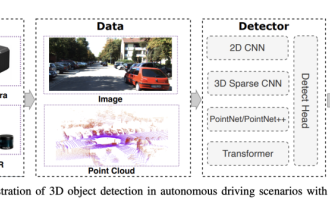 Choose camera or lidar? A recent review on achieving robust 3D object detection
Jan 26, 2024 am 11:18 AM
Choose camera or lidar? A recent review on achieving robust 3D object detection
Jan 26, 2024 am 11:18 AM
0.Written in front&& Personal understanding that autonomous driving systems rely on advanced perception, decision-making and control technologies, by using various sensors (such as cameras, lidar, radar, etc.) to perceive the surrounding environment, and using algorithms and models for real-time analysis and decision-making. This enables vehicles to recognize road signs, detect and track other vehicles, predict pedestrian behavior, etc., thereby safely operating and adapting to complex traffic environments. This technology is currently attracting widespread attention and is considered an important development area in the future of transportation. one. But what makes autonomous driving difficult is figuring out how to make the car understand what's going on around it. This requires that the three-dimensional object detection algorithm in the autonomous driving system can accurately perceive and describe objects in the surrounding environment, including their locations,
 The Stable Diffusion 3 paper is finally released, and the architectural details are revealed. Will it help to reproduce Sora?
Mar 06, 2024 pm 05:34 PM
The Stable Diffusion 3 paper is finally released, and the architectural details are revealed. Will it help to reproduce Sora?
Mar 06, 2024 pm 05:34 PM
StableDiffusion3’s paper is finally here! This model was released two weeks ago and uses the same DiT (DiffusionTransformer) architecture as Sora. It caused quite a stir once it was released. Compared with the previous version, the quality of the images generated by StableDiffusion3 has been significantly improved. It now supports multi-theme prompts, and the text writing effect has also been improved, and garbled characters no longer appear. StabilityAI pointed out that StableDiffusion3 is a series of models with parameter sizes ranging from 800M to 8B. This parameter range means that the model can be run directly on many portable devices, significantly reducing the use of AI
 This article is enough for you to read about autonomous driving and trajectory prediction!
Feb 28, 2024 pm 07:20 PM
This article is enough for you to read about autonomous driving and trajectory prediction!
Feb 28, 2024 pm 07:20 PM
Trajectory prediction plays an important role in autonomous driving. Autonomous driving trajectory prediction refers to predicting the future driving trajectory of the vehicle by analyzing various data during the vehicle's driving process. As the core module of autonomous driving, the quality of trajectory prediction is crucial to downstream planning control. The trajectory prediction task has a rich technology stack and requires familiarity with autonomous driving dynamic/static perception, high-precision maps, lane lines, neural network architecture (CNN&GNN&Transformer) skills, etc. It is very difficult to get started! Many fans hope to get started with trajectory prediction as soon as possible and avoid pitfalls. Today I will take stock of some common problems and introductory learning methods for trajectory prediction! Introductory related knowledge 1. Are the preview papers in order? A: Look at the survey first, p
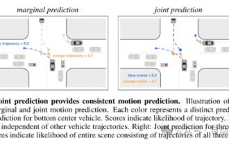
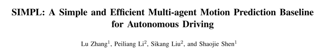 SIMPL: A simple and efficient multi-agent motion prediction benchmark for autonomous driving
Feb 20, 2024 am 11:48 AM
SIMPL: A simple and efficient multi-agent motion prediction benchmark for autonomous driving
Feb 20, 2024 am 11:48 AM
Original title: SIMPL: ASimpleandEfficientMulti-agentMotionPredictionBaselineforAutonomousDriving Paper link: https://arxiv.org/pdf/2402.02519.pdf Code link: https://github.com/HKUST-Aerial-Robotics/SIMPL Author unit: Hong Kong University of Science and Technology DJI Paper idea: This paper proposes a simple and efficient motion prediction baseline (SIMPL) for autonomous vehicles. Compared with traditional agent-cent
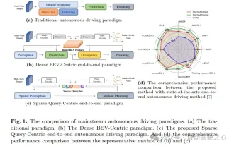 nuScenes' latest SOTA | SparseAD: Sparse query helps efficient end-to-end autonomous driving!
Apr 17, 2024 pm 06:22 PM
nuScenes' latest SOTA | SparseAD: Sparse query helps efficient end-to-end autonomous driving!
Apr 17, 2024 pm 06:22 PM
Written in front & starting point The end-to-end paradigm uses a unified framework to achieve multi-tasking in autonomous driving systems. Despite the simplicity and clarity of this paradigm, the performance of end-to-end autonomous driving methods on subtasks still lags far behind single-task methods. At the same time, the dense bird's-eye view (BEV) features widely used in previous end-to-end methods make it difficult to scale to more modalities or tasks. A sparse search-centric end-to-end autonomous driving paradigm (SparseAD) is proposed here, in which sparse search fully represents the entire driving scenario, including space, time, and tasks, without any dense BEV representation. Specifically, a unified sparse architecture is designed for task awareness including detection, tracking, and online mapping. In addition, heavy
 Let's talk about end-to-end and next-generation autonomous driving systems, as well as some misunderstandings about end-to-end autonomous driving?
Apr 15, 2024 pm 04:13 PM
Let's talk about end-to-end and next-generation autonomous driving systems, as well as some misunderstandings about end-to-end autonomous driving?
Apr 15, 2024 pm 04:13 PM
In the past month, due to some well-known reasons, I have had very intensive exchanges with various teachers and classmates in the industry. An inevitable topic in the exchange is naturally end-to-end and the popular Tesla FSDV12. I would like to take this opportunity to sort out some of my thoughts and opinions at this moment for your reference and discussion. How to define an end-to-end autonomous driving system, and what problems should be expected to be solved end-to-end? According to the most traditional definition, an end-to-end system refers to a system that inputs raw information from sensors and directly outputs variables of concern to the task. For example, in image recognition, CNN can be called end-to-end compared to the traditional feature extractor + classifier method. In autonomous driving tasks, input data from various sensors (camera/LiDAR
