
 Technology peripherals
AI
A must-have for beginners, NeRF study notes provide insight into everything!
Technology peripherals
AI
A must-have for beginners, NeRF study notes provide insight into everything!
A must-have for beginners, NeRF study notes provide insight into everything!

What exactly is the neural radiation field?
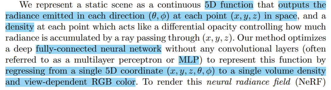
Radiation field: The light emitted by the light source is formed during the propagation and reflection process in the scene Energy distribution. In layman's terms, it is a function that records the radiation information in a certain direction at a certain location in space. The radiation information (or energy distribution) is actually color, brightness, shadow and other information. The direction here requires extra attention, it is one of the important factors for NeRF to achieve real reconstruction!

This leads to the concept of neural radiation field.
Neural Radiation Field: Use neural network to store space position radiation in any direction . The description in the original text is as follows:
The more standardized formula is expressed as follows:
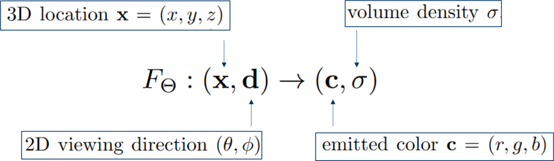
Input 3D position (x,y ,z) and 2D viewing angle direction (), the output is color and volume density
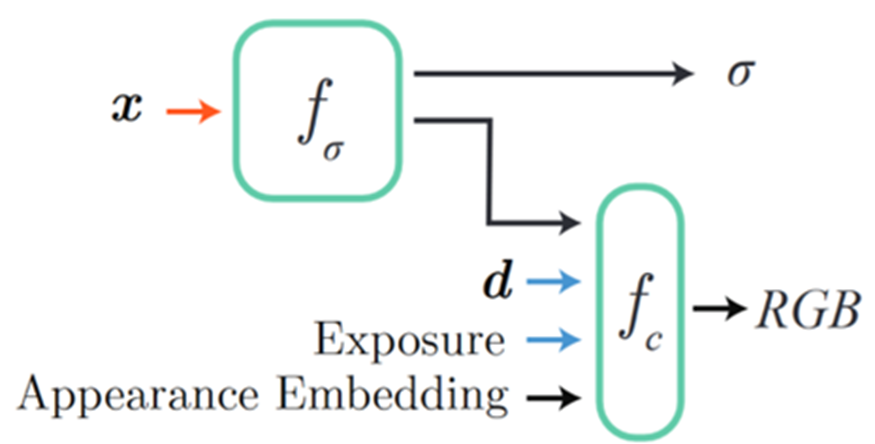
NeRF specific network results refer to the original text as follows:
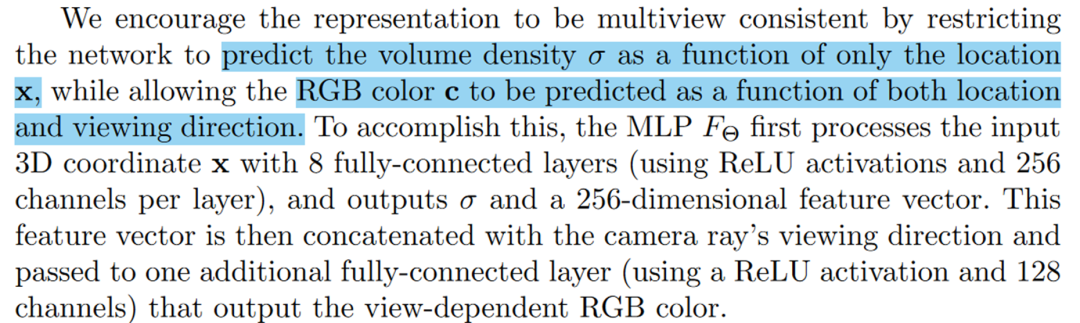
- The 3D coordinates d is sent to fc (one layer, 128 channels, ReLU activation) to predict RGB;
 It can be seen from the above that NeRF is implicit modeling because the model is stored In MLP, the model is the parameter of MLP, which is different from the previous point cloud and mesh modeling (point cloud/mesh can directly see the model). NeRF must query three-dimensional points one by one and then render them into an image. This
or rendering method is called volume rendering. Before looking at volume rendering. Let’s first take a look at the effect of the network:
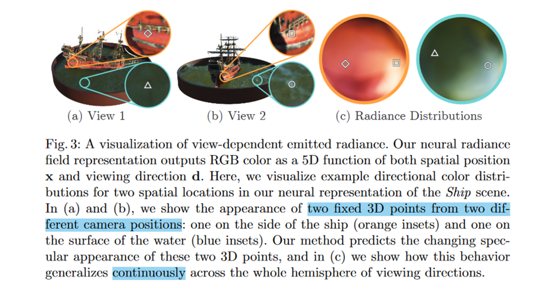 It can be seen that the colors are different under different viewing angles! This is one of the very important advantages of NeRF over traditional reconstruction~
Let’s enter the second core point of NeRF-volume render. Volume rendering is a method used to render color and density into 2D images!
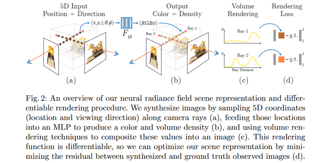
 The schematic diagram is as follows: Figure a shows that a ray is emitted from the optical center position of the camera. There are sampling points on the ray. The sampling points and directions are sent to the MLP to obtain the color and volume density. Figure c shows the volume density distribution curve along the ray, which is obtained through sampling. The color of the pixel can be obtained by integrating the curve. This process is volume rendering
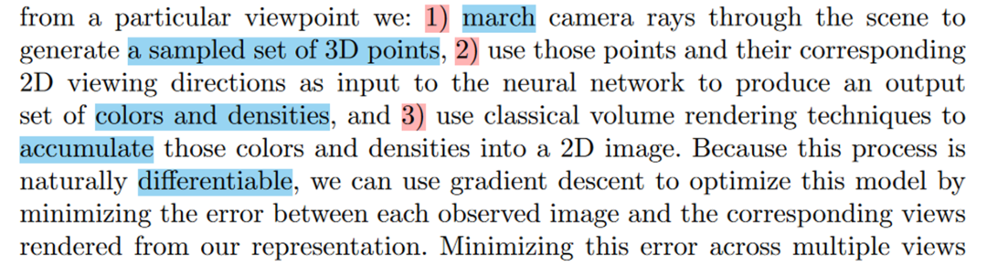
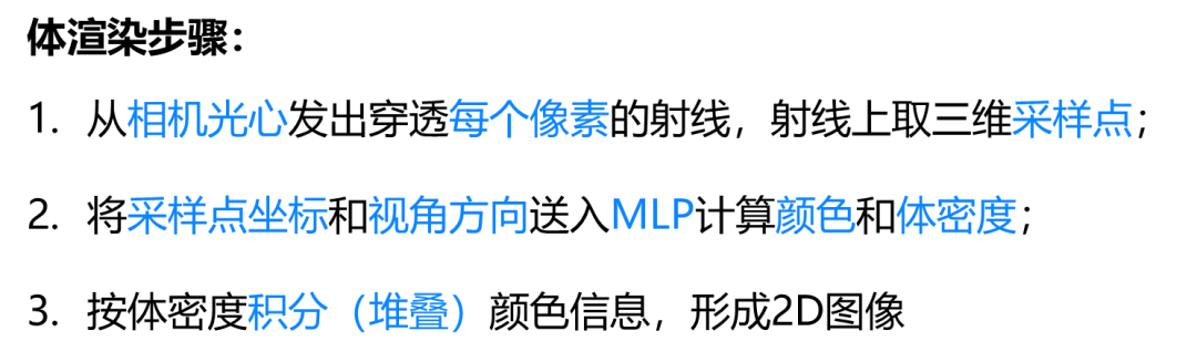
 To summarize the volume rendering steps:
- Send the sampling point coordinates and viewing angle direction to MLP to calculate color and volume density;
- Integrate (stack) color information according to volume density to form a 2D image
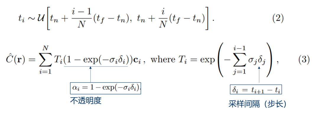
 The formula for volume rendering is as follows:
 Of course, the discrete version of the formula is actually used:
After talking about the neural radiation field and volume rendering, now we start the complete reconstruction process~
In Before forming a completed pipeline, there are still two problems that need to be solved:
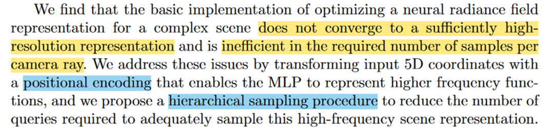 In order to solve the above two problems, NeRF proposed the position encoding and stratified sampling process
Position coding:
 The paper visually shows the comparison of the effects of position coding:
It can be seen that without position coding, the model cannot express high-frequency geometric and texture information~
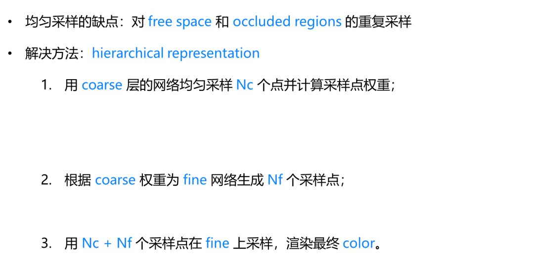
Multi-layer adoption:
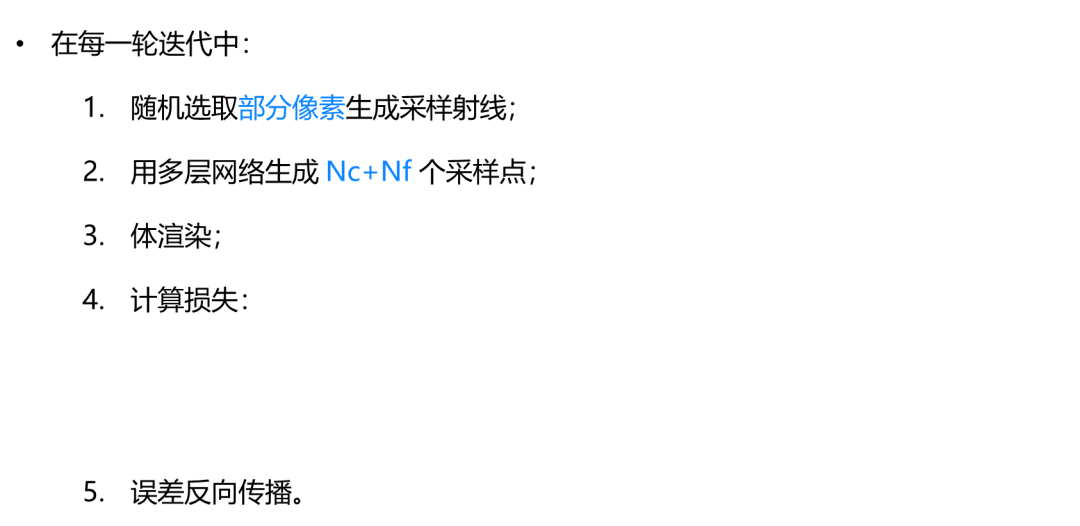
The training process is as follows :
Experiment and summary
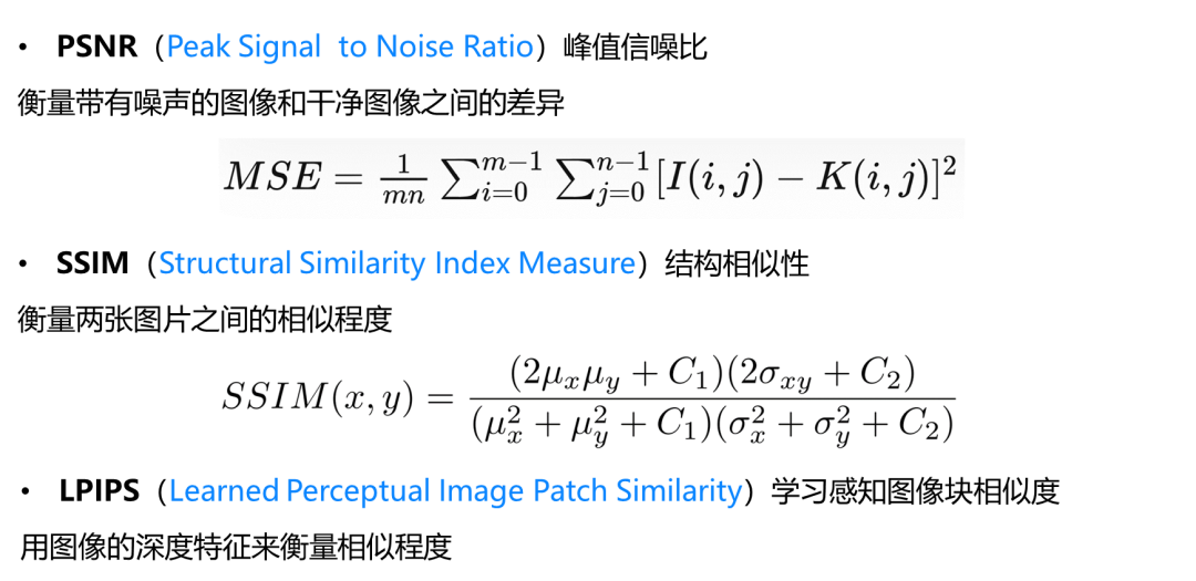
Evaluation indicators:
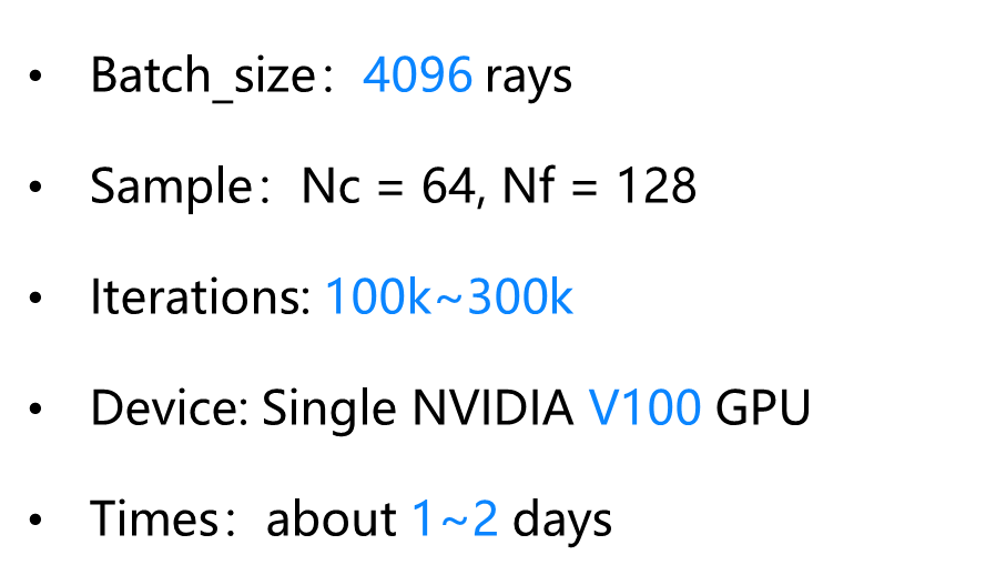
Experiment Settings:
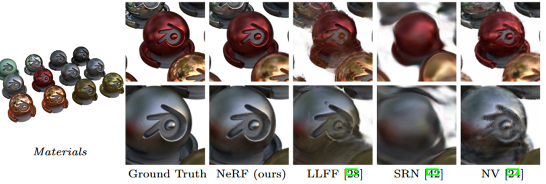
The experimental results show that the astigmatism on balls of various materials can also be well expressed~

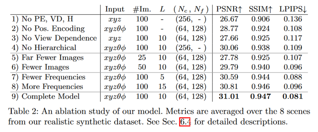
Ablation experiment:
Summary
The neural radiation proposed in the article Field, a sampling ray is emitted from the camera optical center through the pixel, a point is taken on the ray, its three-dimensional position and viewing direction are mapped to volume density and color using an MLP, and then volume rendering is used to stack the volume density and color on the sampling ray. , get the pixel value. The error between the pixel value and the GT image is calculated and then back-propagated to optimize the MLP parameters. This paper uses such an implicit reconstruction method to achieve photorealistic model reconstruction and rendering.
Defects:
- Slow rendering and training speed;
- Have high requirements on the number and distribution of perspectives;
- It is difficult to expand to have backgrounds or larger scenes.

Original link: https://mp.weixin.qq.com/s/ctDBTaLWuHTM9MONrAor4g
The above is the detailed content of A must-have for beginners, NeRF study notes provide insight into everything!. For more information, please follow other related articles on the PHP Chinese website!

Hot AI Tools

Undresser.AI Undress
AI-powered app for creating realistic nude photos

AI Clothes Remover
Online AI tool for removing clothes from photos.

Undress AI Tool
Undress images for free

Clothoff.io
AI clothes remover

Video Face Swap
Swap faces in any video effortlessly with our completely free AI face swap tool!

Hot Article
Hot Tools

Notepad++7.3.1
Easy-to-use and free code editor

SublimeText3 Chinese version
Chinese version, very easy to use

Zend Studio 13.0.1
Powerful PHP integrated development environment

Dreamweaver CS6
Visual web development tools

SublimeText3 Mac version
God-level code editing software (SublimeText3)
Hot Topics


 Why is Gaussian Splatting so popular in autonomous driving that NeRF is starting to be abandoned?
Jan 17, 2024 pm 02:57 PM
Why is Gaussian Splatting so popular in autonomous driving that NeRF is starting to be abandoned?
Jan 17, 2024 pm 02:57 PM
Written above & the author’s personal understanding Three-dimensional Gaussiansplatting (3DGS) is a transformative technology that has emerged in the fields of explicit radiation fields and computer graphics in recent years. This innovative method is characterized by the use of millions of 3D Gaussians, which is very different from the neural radiation field (NeRF) method, which mainly uses an implicit coordinate-based model to map spatial coordinates to pixel values. With its explicit scene representation and differentiable rendering algorithms, 3DGS not only guarantees real-time rendering capabilities, but also introduces an unprecedented level of control and scene editing. This positions 3DGS as a potential game-changer for next-generation 3D reconstruction and representation. To this end, we provide a systematic overview of the latest developments and concerns in the field of 3DGS for the first time.
 How to solve the long tail problem in autonomous driving scenarios?
Jun 02, 2024 pm 02:44 PM
How to solve the long tail problem in autonomous driving scenarios?
Jun 02, 2024 pm 02:44 PM
Yesterday during the interview, I was asked whether I had done any long-tail related questions, so I thought I would give a brief summary. The long-tail problem of autonomous driving refers to edge cases in autonomous vehicles, that is, possible scenarios with a low probability of occurrence. The perceived long-tail problem is one of the main reasons currently limiting the operational design domain of single-vehicle intelligent autonomous vehicles. The underlying architecture and most technical issues of autonomous driving have been solved, and the remaining 5% of long-tail problems have gradually become the key to restricting the development of autonomous driving. These problems include a variety of fragmented scenarios, extreme situations, and unpredictable human behavior. The "long tail" of edge scenarios in autonomous driving refers to edge cases in autonomous vehicles (AVs). Edge cases are possible scenarios with a low probability of occurrence. these rare events
 Choose camera or lidar? A recent review on achieving robust 3D object detection
Jan 26, 2024 am 11:18 AM
Choose camera or lidar? A recent review on achieving robust 3D object detection
Jan 26, 2024 am 11:18 AM
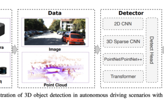
0.Written in front&& Personal understanding that autonomous driving systems rely on advanced perception, decision-making and control technologies, by using various sensors (such as cameras, lidar, radar, etc.) to perceive the surrounding environment, and using algorithms and models for real-time analysis and decision-making. This enables vehicles to recognize road signs, detect and track other vehicles, predict pedestrian behavior, etc., thereby safely operating and adapting to complex traffic environments. This technology is currently attracting widespread attention and is considered an important development area in the future of transportation. one. But what makes autonomous driving difficult is figuring out how to make the car understand what's going on around it. This requires that the three-dimensional object detection algorithm in the autonomous driving system can accurately perceive and describe objects in the surrounding environment, including their locations,
 The Stable Diffusion 3 paper is finally released, and the architectural details are revealed. Will it help to reproduce Sora?
Mar 06, 2024 pm 05:34 PM
The Stable Diffusion 3 paper is finally released, and the architectural details are revealed. Will it help to reproduce Sora?
Mar 06, 2024 pm 05:34 PM
StableDiffusion3’s paper is finally here! This model was released two weeks ago and uses the same DiT (DiffusionTransformer) architecture as Sora. It caused quite a stir once it was released. Compared with the previous version, the quality of the images generated by StableDiffusion3 has been significantly improved. It now supports multi-theme prompts, and the text writing effect has also been improved, and garbled characters no longer appear. StabilityAI pointed out that StableDiffusion3 is a series of models with parameter sizes ranging from 800M to 8B. This parameter range means that the model can be run directly on many portable devices, significantly reducing the use of AI
 This article is enough for you to read about autonomous driving and trajectory prediction!
Feb 28, 2024 pm 07:20 PM
This article is enough for you to read about autonomous driving and trajectory prediction!
Feb 28, 2024 pm 07:20 PM
Trajectory prediction plays an important role in autonomous driving. Autonomous driving trajectory prediction refers to predicting the future driving trajectory of the vehicle by analyzing various data during the vehicle's driving process. As the core module of autonomous driving, the quality of trajectory prediction is crucial to downstream planning control. The trajectory prediction task has a rich technology stack and requires familiarity with autonomous driving dynamic/static perception, high-precision maps, lane lines, neural network architecture (CNN&GNN&Transformer) skills, etc. It is very difficult to get started! Many fans hope to get started with trajectory prediction as soon as possible and avoid pitfalls. Today I will take stock of some common problems and introductory learning methods for trajectory prediction! Introductory related knowledge 1. Are the preview papers in order? A: Look at the survey first, p
 Let's talk about end-to-end and next-generation autonomous driving systems, as well as some misunderstandings about end-to-end autonomous driving?
Apr 15, 2024 pm 04:13 PM
Let's talk about end-to-end and next-generation autonomous driving systems, as well as some misunderstandings about end-to-end autonomous driving?
Apr 15, 2024 pm 04:13 PM
In the past month, due to some well-known reasons, I have had very intensive exchanges with various teachers and classmates in the industry. An inevitable topic in the exchange is naturally end-to-end and the popular Tesla FSDV12. I would like to take this opportunity to sort out some of my thoughts and opinions at this moment for your reference and discussion. How to define an end-to-end autonomous driving system, and what problems should be expected to be solved end-to-end? According to the most traditional definition, an end-to-end system refers to a system that inputs raw information from sensors and directly outputs variables of concern to the task. For example, in image recognition, CNN can be called end-to-end compared to the traditional feature extractor + classifier method. In autonomous driving tasks, input data from various sensors (camera/LiDAR
 SIMPL: A simple and efficient multi-agent motion prediction benchmark for autonomous driving
Feb 20, 2024 am 11:48 AM
SIMPL: A simple and efficient multi-agent motion prediction benchmark for autonomous driving
Feb 20, 2024 am 11:48 AM
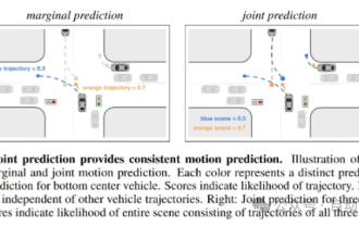
Original title: SIMPL: ASimpleandEfficientMulti-agentMotionPredictionBaselineforAutonomousDriving Paper link: https://arxiv.org/pdf/2402.02519.pdf Code link: https://github.com/HKUST-Aerial-Robotics/SIMPL Author unit: Hong Kong University of Science and Technology DJI Paper idea: This paper proposes a simple and efficient motion prediction baseline (SIMPL) for autonomous vehicles. Compared with traditional agent-cent
 FisheyeDetNet: the first target detection algorithm based on fisheye camera
Apr 26, 2024 am 11:37 AM
FisheyeDetNet: the first target detection algorithm based on fisheye camera
Apr 26, 2024 am 11:37 AM
Target detection is a relatively mature problem in autonomous driving systems, among which pedestrian detection is one of the earliest algorithms to be deployed. Very comprehensive research has been carried out in most papers. However, distance perception using fisheye cameras for surround view is relatively less studied. Due to large radial distortion, standard bounding box representation is difficult to implement in fisheye cameras. To alleviate the above description, we explore extended bounding box, ellipse, and general polygon designs into polar/angular representations and define an instance segmentation mIOU metric to analyze these representations. The proposed model fisheyeDetNet with polygonal shape outperforms other models and simultaneously achieves 49.5% mAP on the Valeo fisheye camera dataset for autonomous driving
