
 Technology peripherals
AI
Microsoft patent sharing for seamless transition between 2D and 3D in Metaverse remote meetings
Technology peripherals
AI
Microsoft patent sharing for seamless transition between 2D and 3D in Metaverse remote meetings
Microsoft patent sharing for seamless transition between 2D and 3D in Metaverse remote meetings

(Nweon December 26, 2023) The development of remote meetings is promoting the popularization of the Metaverse. However, currently online meeting applications face a major problem when using meta-environments, which is that not all participants use the same type of device. For example, some users use PCs, while others use virtual reality headsets
Desktop device users are sometimes at a disadvantage because they cannot navigate or interact with all users in the virtual environment. While a computer provides a 2D view of a 3D environment, the computer is limited in how it receives input gestures from the user to navigate or interact with the 3D environment.
From the current point of view, although technology is developing rapidly, the experience of VR headset users and PC users is not the same. Additionally, existing systems do not allow for seamless transitions from VR headsets to desktop devices or vice versa during events such as parties or company meetings.
In Microsoft's patent application, titled "Rendering of 2D and 3D transitions in user-engaged communication sessions," a related seamless transition method is detailed.
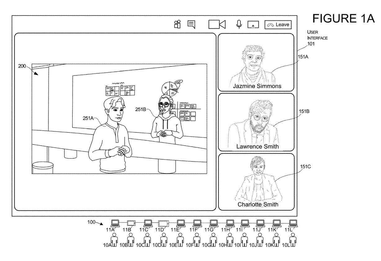
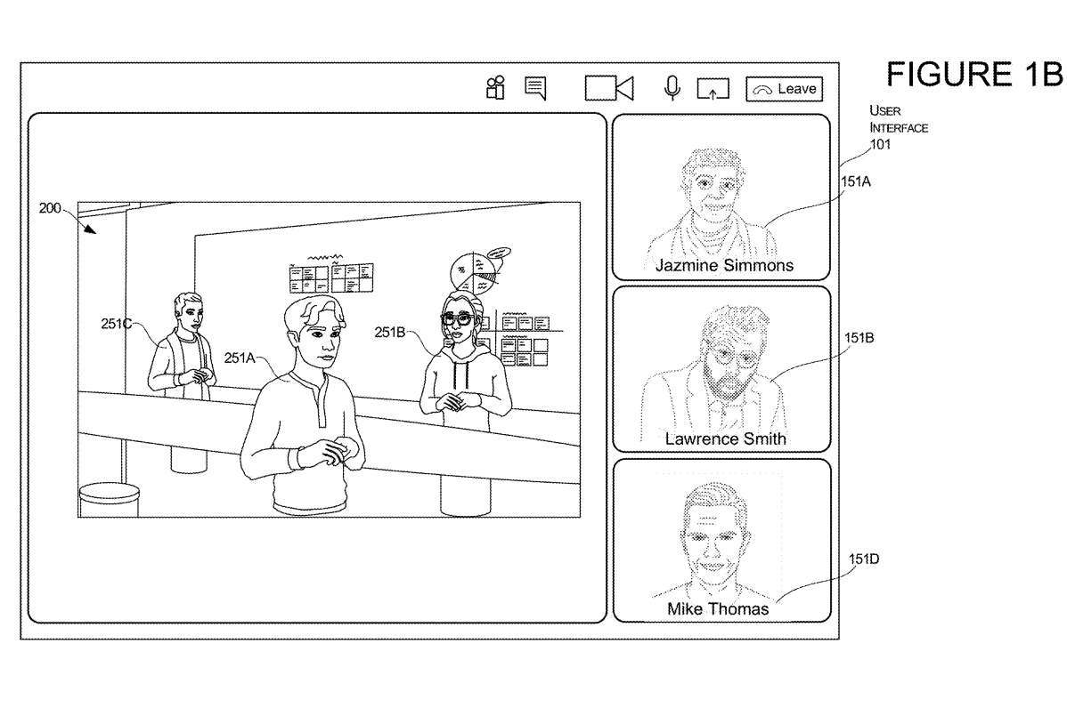
Figures 1A and 1B illustrate the transition of a user interface arrangement from the display of a two-dimensional image of the user to the presentation of a three-dimensional representation of the user while the user is engaged in a communication session.
The communication session may be managed by a system 100 composed of several computers 11, each computer 11 corresponding to several users 10. In this example, the third user 10C's presentation will undergo conversion from 2D mode to 3D mode.
To initiate a transition, the system can receive an input to cause a display transition of a specific user's 2D image presentation. In this example, the input identifies the third user 10C. This input may also provide permission to allow the system to access the 3D model defining the location and orientation for the third user 10C. These positions and directions may include vectors and coordinates represented in 3D environment 200, referred to herein as virtual environment 200.
In response to receiving input, one or more computers of system 100 may make modifications to user interface 101 to remove the rendering of image 151C of user 10C as shown in Figure 1A and to add the rendering of image 151C of user 10C as shown in Figure 1B Rendering of the 3D representation of the User 10C 251C. The presentation of the 3D representation 251C of the user 10C may be positioned and oriented in the 3D environment based on the coordinates and/or vectors defined in the 3D model.In this example, the rendering of user 10C's 2D image is removed and can then be replaced with another rendering. For example, the 2D image rendering of the third user 10C shown in FIG. 1A is replaced in the UI with another 2D image of another user, the fourth user 10D shown in FIG. 1B .
This transformation allows users to interact with computing devices in different ways. For example, in this example, if user 10C wishes to switch from live video streaming in a communication session to another mode of operation that allows the user to interact with other users in a 3D environment, the system will switch the user from one mode Switch to another mode, allowing it to interact with general content, documents, spreadsheets, and slides Switch to a mode that allows it to interact with 3D objects
This transition during a communication session allows selected users to use editing tools appropriate for different content types in each environment. For example, if a person in a video stream wishes to leave the 2D mode using 2D images shown to the user and enter a 3D environment to show other users how to move objects in specific locations or shape specific 3D objects, then once the user is able to By switching, they can do that more easily.
Users can accomplish this conversion using a desktop PC without using any type of XR headset. This transformation using the desktop enables the user to use the desktop computer to enter a 3D mode of interaction with the 3D computing environment, which may be more suitable for editing or viewing certain types of content.
Microsoft noted that one of the technical benefits is that the system can allow users to switch between 3D mode and 2D mode of the communication session regardless of what hardware they are interacting with.
The technology described in the invention is also applicable to head-mounted displays. In such embodiments, the user may remain using only one computing device, such as a head-mounted display, while transitioning the interactive model from a 3D computing environment to a 2D computing environment. Therefore, a user can launch in a 3D computing environment and be represented by a presentation of 3D representation 251C, such as the representation shown in Figure 1B.
Then, in response to one or more inputs, such as a user starting to edit content with a specific file type, or based on input indicating an intent to perform a UI transformation, the system may transform the UI to remove the rendering of the 3D representation 251C, as shown in Figure 1B , and generates a representation of the user's 2D image 151C, such as the representation shown in Figure 1A. This allows users to transition to a 2D environment without actually using a desktop device using a flat screen display and keyboard.
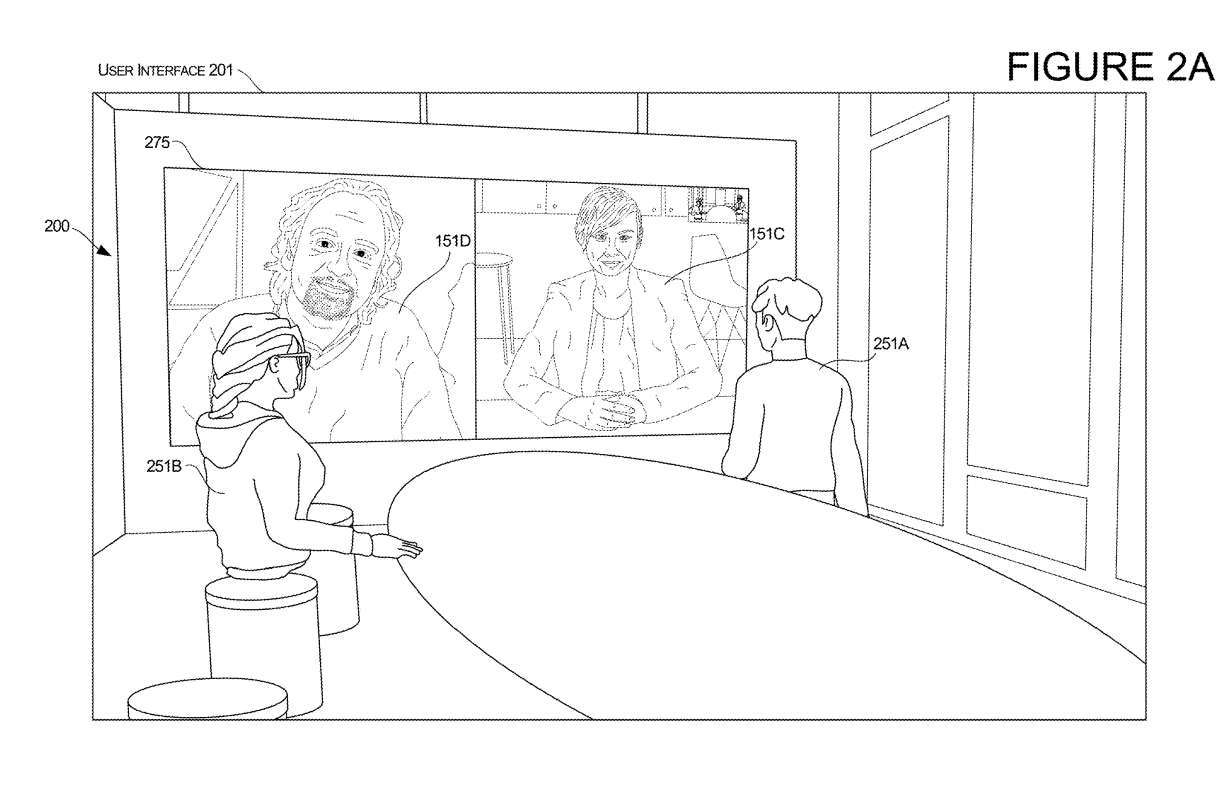
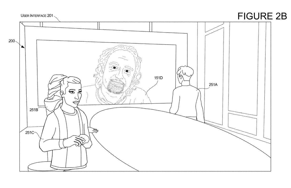
Figures 2A and 2B illustrate another example of a transition of a user interface from a display with a two-dimensional image of the user to a presentation of a three-dimensional representation of the user while the user is participating in a communication session.
In this example, the user interface 201 is a presentation of a 3D environment based on a 3D model. User interface 201 begins with a 3D rendering of representation 251A of first user 10A and a 3D rendering of representation 251B of second user 10B. Each represented 3D rendering has a position and an orientation determined by the virtual object properties stored in the 3D model
The 3D environment also includes a virtual object 275 in the form of a virtual flat screen television mounted on the wall of the virtual environment. Virtual object 275 has a display surface that displays a virtual user interface that displays a 2D rendering 151C of the third user 10C and a 2D rendering 151D of the fourth user 10D.
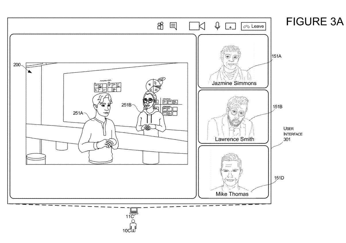
Figures 3A and 3B illustrate another aspect of third-user conversion. In this example, the presentation of the third user 10C undergoes conversion from the 2D mode to the 3D mode.
As shown in Figure 3A, the user interface 301 first displays two-dimensional images of Jessamine, Lawrence and Mike, which are displayed as renderings of images 151A, 151B and 151D respectively. The user interface simultaneously includes a presentation of the 3D environment 200 with two 3D representations 251A and 251B of other users.
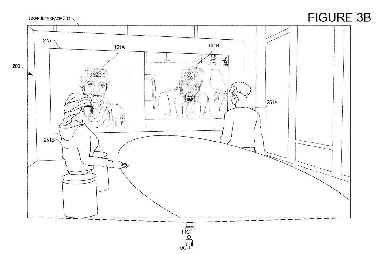
In response to the input data described in this article, the system performs transformations. In the transition of the third user, the third computer 11C of the third user 10C transitions from the user interface shown in FIG. 3A to the user interface shown in FIG. 3B.
After conversion, Charlotte's computer 11C displays the modified user interface 301, as shown in Figure 3B. The system will maintain the state of each user, just like the three-dimensional representation of the two users 251A and 251B shown in Figure 3A, and also maintain the three-dimensional representation of 251A and 251B shown in Figure 3B
Also shown in Figure 3B, the modified user interface 301 includes a virtual object 275, which in this case is a virtual display device that displays a 2D rendering of other users that was originally displayed as a 2D image, such as Figure 3A Jessamine and Laurence in .
This modified 301 UI now displays Charlotte's perspective as if she teleported from a 2D environment to a 3D environment. Similar to the other examples, in this teleportation the system can determine the Charlotte Avatar's position and direction based on one or more factors.
In such an example, Charlotte might be operating a device, such as a PC. Then, in response to one or more inputs described herein, the system can transition from the user interface of Figure 3A to the user interface of Figure 3B while continuing to use the desktop PC. This example transition can be achieved even without using a headset traditionally used for viewing 3D renderings.
In another example, the transition may involve Charlotte starting with the user interface of Figure 3B and then transitioning to the user interface of Figure 3A. In this example, Charlotte might be operating a separate device, such as a head-mounted display. She first navigates the 3D environment shown in Figure 3B, and then by reacting to one or more inputs described in this article, the system can transition from the user interface of Figure 3B to the user interface of Figure 3A and continue to use the headset . This example conversion is possible even without using a computer traditionally used to view 2D images
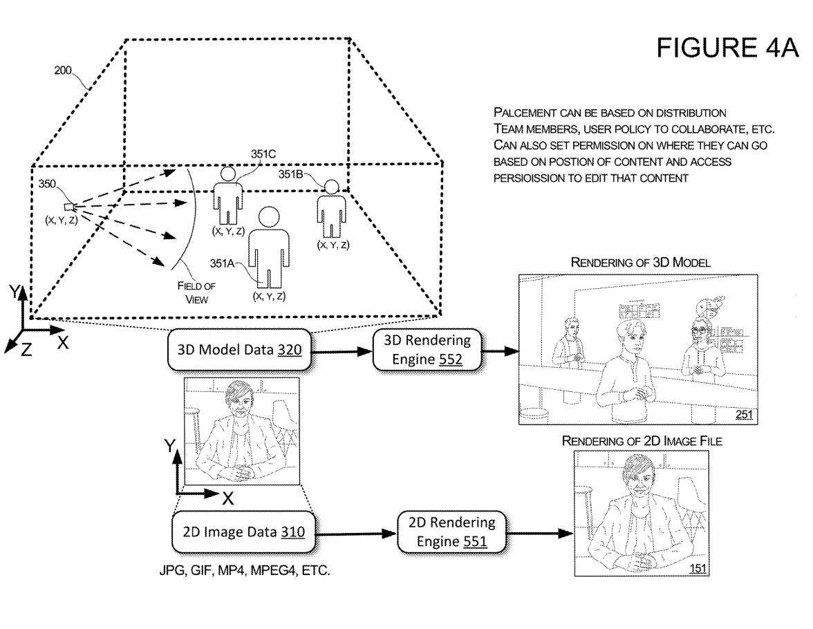
Figure 4A illustrates other features of UI transitions. When receiving input that causes the UI to transition from a presentation of a 2D image of user 1OC to a presentation of a 3D representation of user 1OC, the system may determine the position and orientation of the 3D representation of user 1OC.
For example, if a model starts with only two virtual objects 351A and 351B representing users in the virtual environment 200, then the system can determine the position and direction of the newly added virtual object 351C representing the user. In this example, when the input indicates a particular user, such as third user 10C, the system may determine the location of virtual object 351C representing third user 10C based on the location of other users in virtual environment 200 and/or the location of shared content. Location and direction
In one illustrative example, if the system determines that virtual object 351C representing third user 10C is to be added to virtual environment 200, the system may position virtual object 351C in a manner such that virtual object 351C is presented Out user's avatar is viewing content shared with user 10C.
In another example, if the system determines that virtual object 351C representing a third user 10C is to be added to virtual environment 200, the system may position virtual object 351C in a manner such that it appears to be the user Avatar is talking to user 10C Avatar Conversation
In one embodiment, the placement of each virtual object 351 may be based on distribution among team members, user groups, and/or policies established by individual users or user groups. For example, if a person is part of a corporate team, when one of them is identified in input to the transformation user interface, their corresponding avatar will be positioned within a threshold distance of other team members.
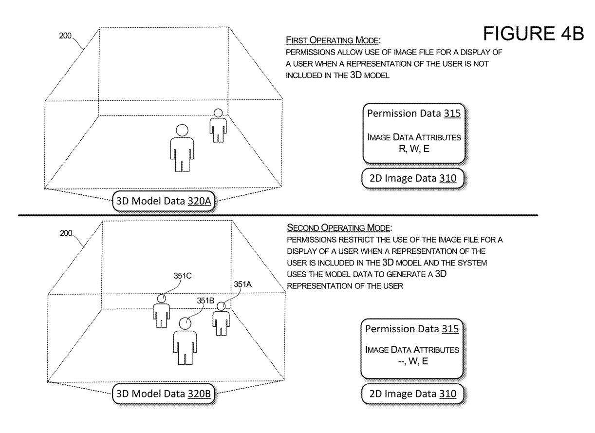
Figure 4B illustrates the two modes of operation of the system and how each mode of operation changes the permissions of individuals participating in a communication session. In a first mode of operation in the upper part of Figure 4B, when a representation of the user is not included in the 3D model, permissions may allow the system to use an image file to display a 2D image of the user.
In this case, the 3D model data is in the first state 320A, in which the selected user has no virtual object representing the user in the 3D environment 200. When the 3D model is in this state, the selected user has no virtual object representing that user in the 3D environment and the permissions data 315 associated with the user is configured to allow the system and other users to access the user's image data 310 . This means that the system and each remote user's client can use the image data 310 to generate a representation of that user, or the system can edit the image data 310 .
When the system detects that the 3D model data is in the second state, for example, the model data 320B contains a virtual object 351C representing the selected user, the system will modify the permissions to limit the use of the image data by the specific user. As shown in the figure, the system will modify the permission data 315 to restrict the system from reading the image data 310 to display the 2D image of the specific user. In this mode of operation, permissions are configured to restrict access to image data to all users, thus preventing all clients from accessing or displaying 2D image files
Figures 5A and 5B illustrate features of a system configured to locate a user's representation in a 3D environment 200 relative to shared content.
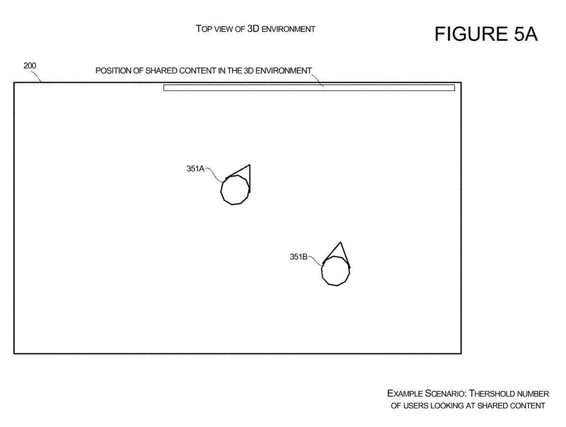
Avatar orientation for the first user 351A and the second user 351B is shown in Figure 5A for a scenario of viewing shared content in a 3D environment. The content they share can be displayed on virtual objects, such as virtual displays. When the system detects that a certain number of users are viewing shared content, the system will generate directions into the 3D environment for the third user with Avatar
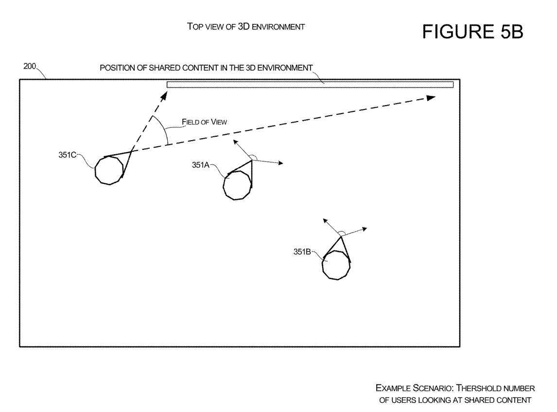
An example offeatures is shown in Figure 5B. In this example, the third user 351C's Avatar is added to the virtual environment. The third user 351C's Avatar points to the shared content in response to the system detecting that the other user has shared content within its field of view. The system can also determine the geometry of each person's field of view and determine the position of the third user's Avatar so that the third user's Avatar does not block other users' fields of view.
Figures 6A and 6B illustrate configurations configured to be positioned relative to other users in the 3D environment 200. Figure 6A illustrates a scenario in which a first user's and a second user's Avatars are oriented such that the users are looking at each other in the virtual environment.
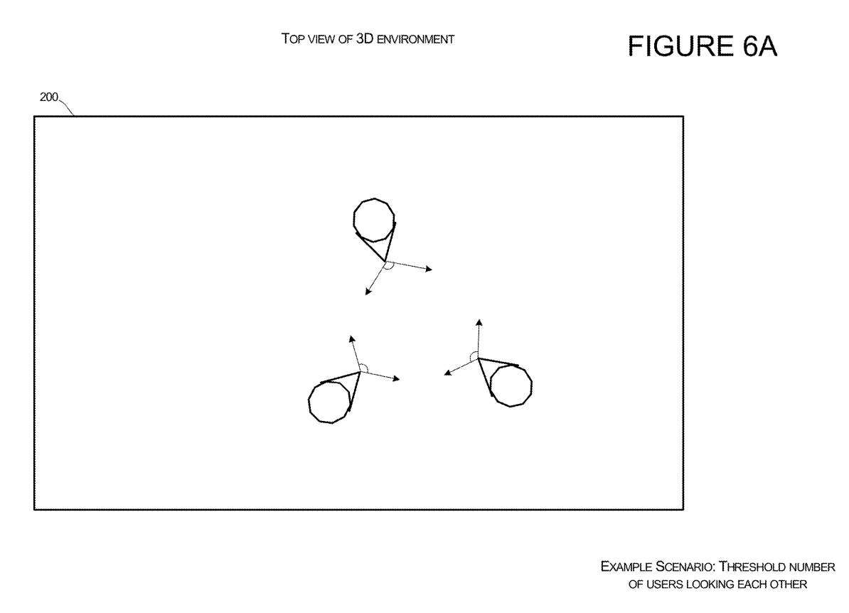
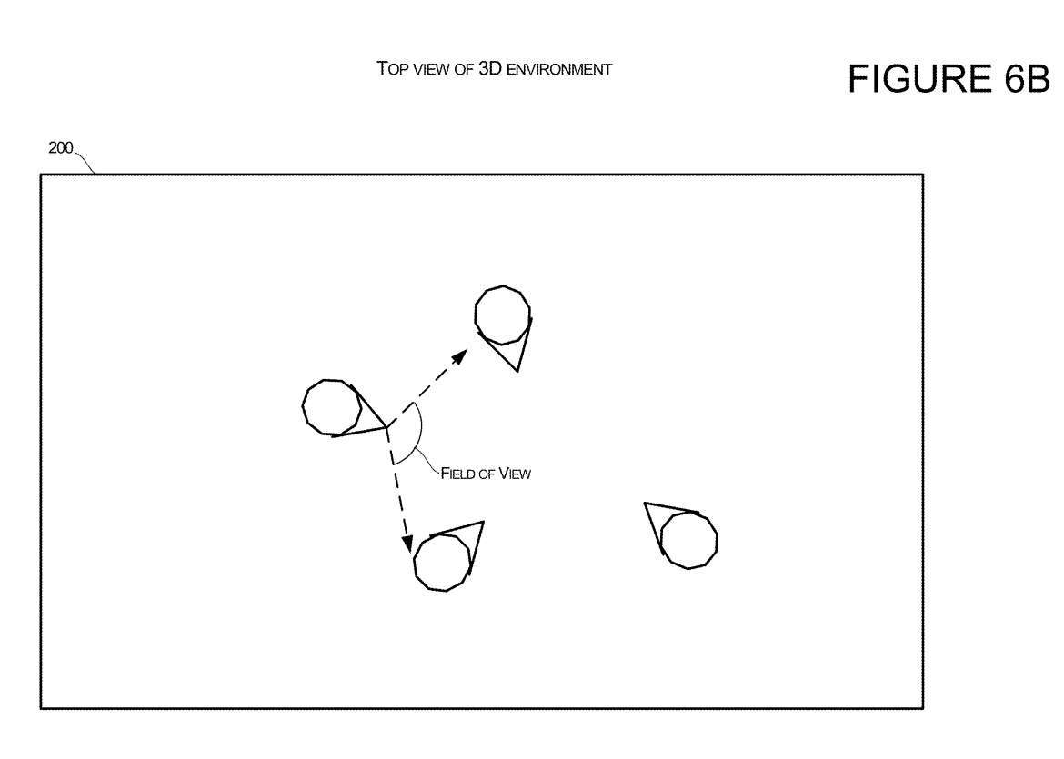
In a specific team or predetermined group, when the system determines that a certain number of people are looking at each other, the system can position the Avatar of the third user entering the environment so that the Avatar's position can be looked at other people. user. Figure 6A shows several avatars with at least three users with other group members within the field of view. When the system determines that a certain threshold number of virtual characters have other group members within the field of view, as shown in Figure 6B, the system can allow new group members to join the virtual environment with a location and orientation that allows the user to view other group members.
Related Patents: Microsoft Patent | 2d and 3d transitions for renderings of users participating in communication sessions
The Microsoft patent application titled "2d and 3d transitions for renderings of users participating in communication sessions" was originally submitted in May 2022 and was recently published by the US Patent and Trademark Office.
It should be noted that, generally speaking, after a U.S. patent application is reviewed, it will be automatically published 18 months from the filing date or priority date, or it will be published within 18 months from the filing date at the request of the applicant. Note that publication of a patent application does not mean that the patent is approved. After a patent application is filed, the USPTO requires actual review, which can take anywhere from 1 to 3 years.
The above is the detailed content of Microsoft patent sharing for seamless transition between 2D and 3D in Metaverse remote meetings. For more information, please follow other related articles on the PHP Chinese website!

Hot AI Tools

Undresser.AI Undress
AI-powered app for creating realistic nude photos

AI Clothes Remover
Online AI tool for removing clothes from photos.

Undress AI Tool
Undress images for free

Clothoff.io
AI clothes remover

AI Hentai Generator
Generate AI Hentai for free.

Hot Article
Hot Tools

Notepad++7.3.1
Easy-to-use and free code editor

SublimeText3 Chinese version
Chinese version, very easy to use

Zend Studio 13.0.1
Powerful PHP integrated development environment

Dreamweaver CS6
Visual web development tools

SublimeText3 Mac version
God-level code editing software (SublimeText3)
Hot Topics
 1376
1376
 52
52

 SUPRA Coin Price Prediction for 2025
Dec 09, 2024 pm 12:11 PM
SUPRA Coin Price Prediction for 2025
Dec 09, 2024 pm 12:11 PM
SUPRA coin, a cryptocurrency that supports a wide range of decentralized applications, has attracted much attention from investors. Its potential price movement depends on factors such as team strength, ecosystem growth, market trends, regulatory environment and competitor performance. Experts predict that SUPRA coin may reach $0.60 to $1 in 2025. The project’s technical foundation, growing ecosystem, and market optimism provide support for its price increase.
 When will the bull run for SuperVerse coins arrive?
Oct 12, 2024 am 07:55 AM
When will the bull run for SuperVerse coins arrive?
Oct 12, 2024 am 07:55 AM
The timing of the SuperVerse coin bull run depends on market conditions, project progress and investor confidence. The exact timing cannot be predicted, but it may occur in the coming months or years, provided that market sentiment is optimistic, the competitive landscape is favorable, projects are progressing smoothly, and investor confidence is high.
 The impact of Ethereum upgrade on ETH price: short-term volatility and long-term value
Feb 27, 2025 pm 04:51 PM
The impact of Ethereum upgrade on ETH price: short-term volatility and long-term value
Feb 27, 2025 pm 04:51 PM
There are two aspects of short-term volatility and long-term value in the impact of Ethereum upgrade on ETH price. In the short term, market expectations before upgrading will affect price rise and fall, technical problems during the upgrade process may lead to price plummeting, and after upgrading, the phenomenon of "selling expectations and buying facts" may occur. In the long run, successful upgrades will improve network performance, such as increasing throughput and reducing transaction fees, and optimizing economic models, such as achieving deflation, thereby increasing the scarcity of ETH and supporting price increases.
 What are the Grayscale Encryption Trust Funds? Common Grayscale Encryption Trust Funds Inventory
Mar 05, 2025 pm 12:33 PM
What are the Grayscale Encryption Trust Funds? Common Grayscale Encryption Trust Funds Inventory
Mar 05, 2025 pm 12:33 PM
Grayscale Investment: The channel for institutional investors to enter the cryptocurrency market. Grayscale Investment Company provides digital currency investment services to institutions and investors. It allows investors to indirectly participate in cryptocurrency investment through the form of trust funds. The company has launched several crypto trusts, which has attracted widespread market attention, but the impact of these funds on token prices varies significantly. This article will introduce in detail some of Grayscale's major crypto trust funds. Grayscale Major Crypto Trust Funds Available at a glance Grayscale Investment (founded by DigitalCurrencyGroup in 2013) manages a variety of crypto asset trust funds, providing institutional investors and high-net-worth individuals with compliant investment channels. Its main funds include: Zcash (ZEC), SOL,
 Comprehensive interpretation of ETH upgrade: the technological revolution from PoW to PoS
Feb 27, 2025 pm 04:27 PM
Comprehensive interpretation of ETH upgrade: the technological revolution from PoW to PoS
Feb 27, 2025 pm 04:27 PM
This article comprehensively interprets the major upgrade of Ethereum from the Proof of Work (PoW) mechanism to the Proof of Stake (PoS) mechanism. Because the PoW mechanism has limitations such as high energy consumption and low efficiency, and cannot meet the industry's growing demand for blockchain scalability, speed and efficiency, Ethereum has launched this upgrade. The article compares the principles and advantages and disadvantages of the two mechanisms PoW and PoS, elaborates on the key upgrade processes such as "The Merge", Dencun upgrade and future sharding, and analyzes the impact of this upgrade on economic model, ecosystem, developers, users and miners, and finally discusses the technical, community and supervision challenges faced during the upgrade process.
 The latest version of the top ten exchanges in the currency circle 2025
Mar 05, 2025 pm 09:12 PM
The latest version of the top ten exchanges in the currency circle 2025
Mar 05, 2025 pm 09:12 PM
This article lists the top ten exchanges in the cryptocurrency circle in 2025, predicts that Binance, OKX, Bitget and Gate.io will become leading exchanges, and analyzes six potential exchanges including Coinbase, Kraken, Bybit, MEXC, Bitfinex and KuCoin. The article deeply explores the advantages, disadvantages and future development potential of each exchange, and looks forward to the four major development trends of currency exchanges in 2025: compliance, derivatives trading growth, social trading and communityization, and the integration of Web3 and meta-universe. Finally, the article reminds readers to pay attention to factors such as security, liquidity, transaction fees, trading products, user experience, customer service and regulatory environment when choosing an exchange, and emphasizes the number of investments.
 Ethereum 2.0 comprehensive analysis: The path to transformation from PoW to PoS
Feb 27, 2025 pm 05:03 PM
Ethereum 2.0 comprehensive analysis: The path to transformation from PoW to PoS
Feb 27, 2025 pm 05:03 PM
The transformation of Ethereum 2.0 from PoW to PoS is a major change in blockchain. The transformation stems from PoW's high energy consumption and poor transaction processing capabilities, which cannot meet the industry's development needs. The "merger" will be completed in September 2022, and there will be subsequent upgrade plans such as sharding. PoW and PoS have obvious differences in principle and advantages and disadvantages. Transformation affects economic models and ecosystems, and also faces challenges at technology, community, and regulatory levels, aiming to improve Ethereum's scalability, transaction speed and energy efficiency.
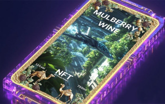 All Things Flower creates the first AI music NFT wine label to set off a new height of integration of intelligent digitalization and culture
Mar 05, 2025 pm 05:42 PM
All Things Flower creates the first AI music NFT wine label to set off a new height of integration of intelligent digitalization and culture
Mar 05, 2025 pm 05:42 PM
AllThingsFlower: AI empowers and leads the digitalization 3.0 era of wine industry! AllThingsFlower has once again innovated the industry and launched innovative products that integrate AI music, mulberry purple wine and NFT digital wine labels, perfectly combining culture and technology, achieving a comprehensive upgrade from product to cultural output, and pointing out the direction for the future development of the wine industry. Each NFT wine label is generated by AIVA.ai's AI algorithm, perfectly integrating the mellow fragrance of mulberry purple wine, the heritage of Silk Road culture with the infinite possibilities of future technology. AI Manufacturing: The digital transformation of traditional wine industry is different from traditional wine brands. AllThingsFlower is committed to the in-depth binding of physical products and digital assets.
