According to a report by Yingwei.com on December 28, 2023, technology giants such as Apple and Meta are exploring various input methods for augmented reality (AR) and virtual reality (VR), including rings. At the same time, Microsoft is conducting similar research. In a patent application titled "Wearable device enabling multi-finger gestures," Microsoft introduced a ring controller that can be used to control related terminal devices, such as headsets. This technology is expected to bring more innovation to the AR/VR field.
In one embodiment, a wearable device such as a ring includes two sensors and a controller. The first sensor is configured to detect one or more movements of a first finger of the user, and the second sensor is configured to detect one or more movements of a second finger that is different from the first finger.
The controller is configured to determine relative motion between the first finger and the second finger based on the motion of the first and second finger. This relative movement can define a multi-finger gesture. The controller can then control an associated end device, such as a head-mounted display, based on multi-finger gestures.
A wearable device 100 such as a ring can be worn on the user's finger. The wearable device 100 is equipped with a set of sensors to detect the relative movement of two or more fingers, such as a first finger 201 and a second finger 202 . The wearable device 100 recognizes a multi-finger gesture based on this relative movement of different fingers, and then controls the associated terminal device 300 based on the multi-finger gesture. In this way, users can control and interact with end devices more efficiently and flexibly.
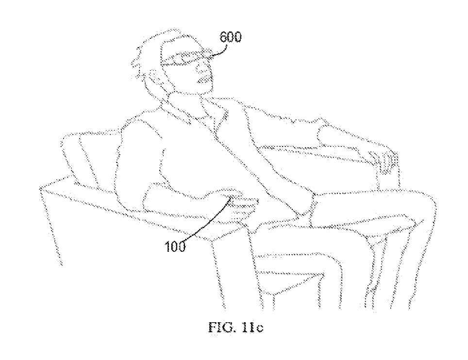
As shown in Figure 11c, a wearable device 100 such as a ring is used with a head-mounted display. Microsoft said that existing methods of controlling the headset use voice, hover gestures or traditional controllers. However, voice control will inevitably involve privacy issues, and hover gestures can cause severe fatigue. In contrast, wearable device 100 does not require the user to raise a hand and is private enough to be done in a pocket.
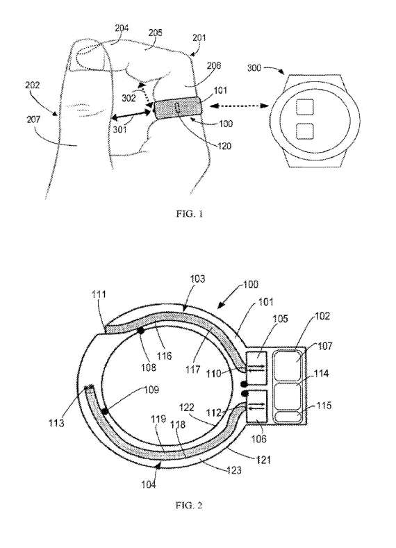
As shown in Figure 2, this is an example showing the structure of the wearable device 100. The wearable device 100 adopts a ring-shaped housing 101, which is composed of an outer side 121, an inner side 122 and a side portion 123 therebetween.
The wearable device 100 includes at least two sensors 105 and 106, respectively referred to as the first sensor 105 and the second sensor 106. These two sensors are used to detect the movement of at least two different fingers of the user.
The first sensor 105 and/or the second sensor 106 may be infrared proximity sensors. Infrared proximity sensors have the characteristics of small size, light weight, low power consumption and low cost, making wearable devices further lightweight and low-power consumption. It should be understood that other kinds of distance measurement sensors such as optical sensors, capacitive sensors and ultrasonic sensors can be used. When light transmission is not required, it can be omitted or adjusted to other structures as needed.
The first sensor 105 is configured to detect at least one movement of the first finger 201 or a segment thereof, and the second sensor 106 is configured to detect at least one movement of the second finger 202 or a segment thereof.
One or both of the first and second sensors 105, 106 may detect movement of multiple portions of the corresponding finger. Compared with high-intensity movements, the finger movements 105, 106 that need to be detected by the first and second sensors are only relative movements between two different fingers. This is a very subtle movement that requires small muscle movements and no hand movements. Therefore, the movements that need to be detected are less tiring, allowing the user to wear the wearable device 100 for a long time like wearing a regular ring.
In addition, only two fingers are required to participate in the interaction, which is preferable to one-handed operation because the other three fingers can still perform other tasks, such as holding a bag.
The wearable device 100 also includes a control module 102. The control module 102 may include a controller 107, a battery 115, and a communication module 114. As shown in Figure 2, the control module 102 may be disposed on top of an annular housing 101, similar to the diamond shape on top of a diamond-shaped housing. This allows the thickness of the annular housing 101 to be reduced. For example, the thickness of the housing 101 can be less than 1 mm and can be easily worn all day long without any discomfort.
The controller 107 determines the relative movement between the two fingers 201 and 202 by receiving and analyzing the movement data of the fingers detected by the first and second sensors 105 and 106. Such relative movement between two fingers defines a two-finger gesture. In addition, since only fairly simple and tiny finger movements need to be detected, the controller 107 can be implemented as a low-power and low-cost miniature microcontroller, such as an 8-bit MCU. This can further reduce the size of the wearable device 100.
In order to detect the movement of the fingers 201, 202, the wearable device 100 may include a plurality of conductor components, such as a first conductor component 103 and a second conductor component 104. The first conductor component 103 has a first end 110 and a second end 111 . The first end 110 is coupled to the first sensor 105 , and the second end 111 faces the first finger 201 . Likewise, the second conductor assembly 104 may have a third end 112 coupled to the second sensor 106 and a fourth end 113 facing the second finger 202 . In this way, by lining up the orientation of the two ends of the conductor assembly, the movements of different fingers can be detected.
The second end 111 and the fourth end 113 may be located at the bottom of the annular housing 101, as shown in Figure 2. At least one of the second end 111 and the fourth end 113 may be located anywhere between the bottom and the sides of the annular housing 101 .
The first conductor component 103 is composed of a first optical fiber 116 and a second optical fiber 117. For example, first optical fiber 116 and second optical fiber 117 may be disposed in first channel 108 within housing 101 . The first channel 108 is a hollow structure that can reduce the weight of the wearable device 100 .
Module 102 is used to control the system, which includes a communication module 114 for communicating with the terminal device 300 in Figure 1. The terminal device 300 may be wired or wireless. The communication module 114 may use a Bluetooth low energy based module.
With reference to Figure 2, the control module 102 may include a battery 115. Because the power consumption of the controller 107, the first and second sensors 105, 106, and other necessary components is very low, the size of the battery 115 can be very small.
Below are examples of multi-finger gestures.
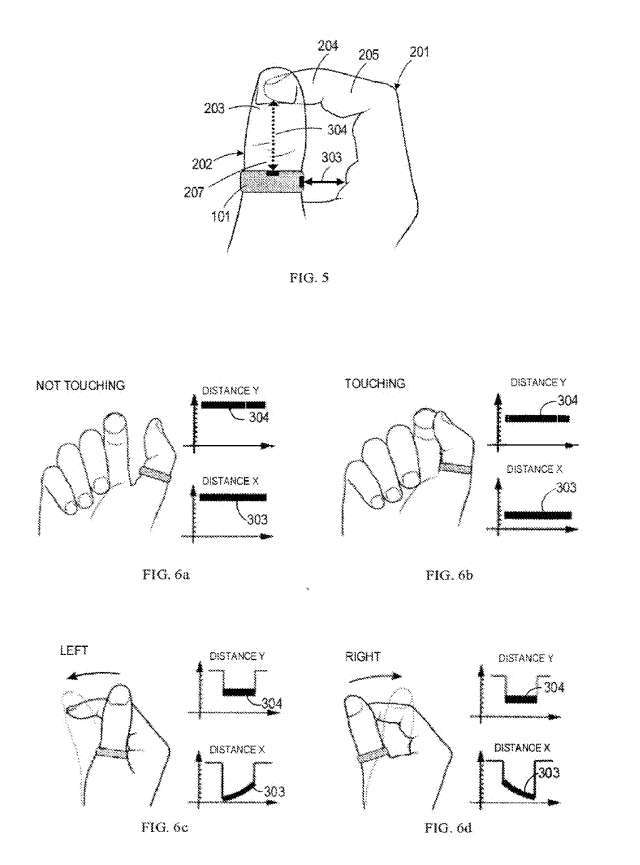
Referring to Figure 1, in this example, it is assumed that the wearable device 100 is worn on the base segment 206 of the index finger 201. In this case, the second end 111 of the first conductor component 103 faces the side of the thumb 202 so that the first sensor 105 can detect the first distance 301 from the side of the thumb 202 to the first sensor 105 .
Move the fourth end 113 of the second conductor component 103 toward the ventral part of the middle part 205 of the index finger 201, so that the second sensor 106 can detect from the ventral part of the middle part 205 of the index finger 201 to the second sensor The second distance of 106 is 302.
Due to the small size of the annular housing 101, the first distance 301 is substantially the relative distance from the lateral portion of the thumb 202 to the base segment 206 of the index finger 201, while the second distance 302 is substantially the ventral portion of the middle portion 205 The relative distance to the base segment 206 of the index finger 201. In this way, the first and second sensors 105, 106 can detect one or more sets of motion.
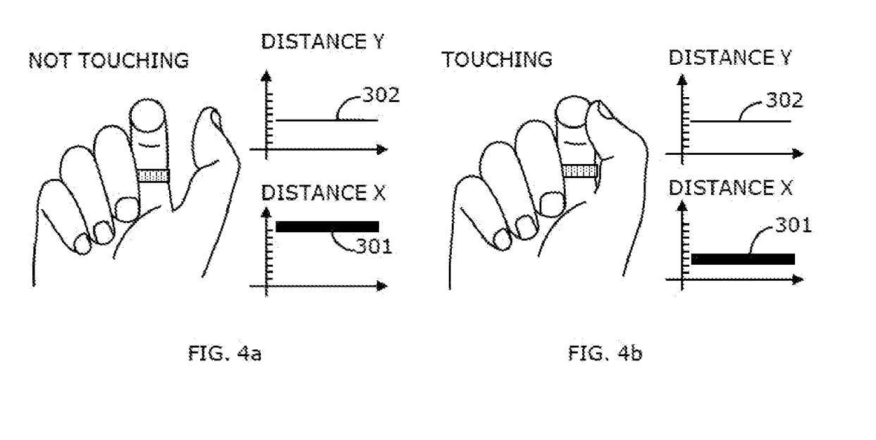
According to the single-action gesture mode shown in Figure 4a, when the thumb 202 does not contact the index finger 201 and remains stationary, the distance detected by the first sensor 105 (called distance X 301) and the distance detected by the second sensor 106 (called distance Y 302) remains unchanged. For example, distance X301 remains as X1 and distance Y302 remains as Y1.
In this scenario, we can see that the thumb 202 in the picture contacts the index finger 201 and remains still. In this case, the distances respectively detected by the first sensor 105 and the second sensor 106 remain unchanged. However, since the position of thumb 202 has changed, distance x301 remains X2, which may be less than X1.
In this case, the value of the distance X can indicate whether the thumb 202 contacts the index finger, which in turn can indicate whether the movement starts or ends. It can be seen that the controller 107 can detect the multi-finger gesture by determining the relative distance between the first and second fingers 201 and 202 .
In one embodiment, the controller 107 may detect a multi-finger gesture by determining a correlated slide between the first and second fingers 201, 202 based on the first and second sets of actions. In response to different sliding directions, the controller 107 can trigger different actions.
When the controller 107 detects that the first finger 201 slides along the second finger 202 from left to right, it triggers a specific action associated with the terminal device 300. Similarly, when the controller 107 detects that the first finger 201 slides along the second finger 202 from right to left, it will also trigger another specific action associated with the terminal device 300.
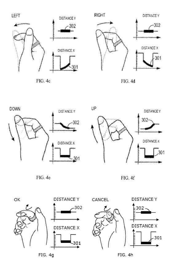
Figures 4c-4d show how distance X 301 and distance Y 302 will change when the thumb 202 slides along the index finger. When the ventral side of the thumb 202 slides from left to right along the index finger 201 , the second sensor 106 can detect the sliding of the thumb 202 and send the detected data to the controller 107 . At the same time, the first sensor 105 can detect that the index finger 201 maintains its position and sends the detected data to the controller 107, as shown in Figure 4d.
Based on the above-mentioned first and second sets of movements, the controller 107 may detect the multi-finger gesture by determining the above-mentioned relative movements between the index finger 201 and the thumb 202. Then, based on the multi-finger gesture, the controller 107 triggers an action associated with the terminal device 300 .
For example, the controller 107 may generate a control signal corresponding to the "right" operation to control the terminal device 300. Similarly, for the ventral side of the thumb 202 to slide from right to left along the index finger 201, as shown in FIG. 4c, based on the multi-finger gesture detected by determining the above-mentioned relative motion between the index finger 201 and the thumb 202, the controller 107 generates A control signal corresponding to the "left" operation and triggering an action associated with the terminal device 300 .
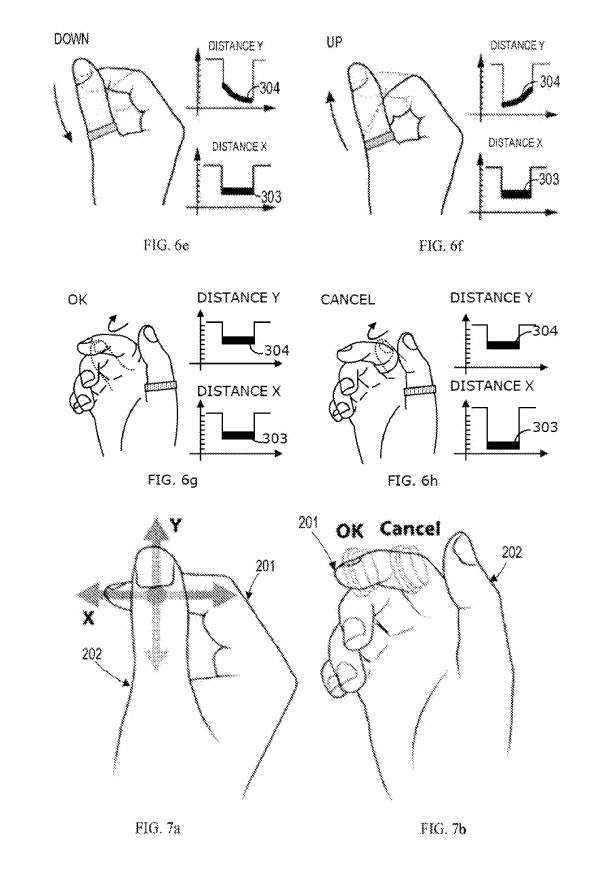
Figures 4e-4f show the changes in distance X 301 and distance Y 302 when the index finger 201 slides up and down along the thumb 202. Similar to the above, when the side part of the index finger 201 slides downward along the thumb 202 , the second sensor 106 can detect that the ventral part of the middle section 205 of the index finger 201 is moving downward, and send the detected data to the controller 107 . At the same time, the first sensor 105 can detect that the thumb 202 is in a still state, and send the detected data to the controller 107, as shown in Figure 4e.
Based on the above-mentioned first and second sets of movements, the controller 107 may detect the multi-finger gesture by determining the above-mentioned relative movements between the index finger 201 and the thumb 202. Then, based on the multi-finger gesture, the controller 107 triggers an action associated with the terminal device 300 and controls the terminal device 300 by generating a control signal corresponding to the "down" operation, as shown in Figure 4e.
Similarly, for the multi-finger gesture detected by determining the above-mentioned relative movement between the index finger 201 and the thumb 202 as shown in Figure 4f, for the ventral part of the middle section 205 of the index finger 201 to slide upward along the thumb 202, the controller 107 triggers an action associated with the terminal device 300 by generating a control signal corresponding to the "up" operation.
In one embodiment, the controller 107 may detect the tapping gesture by determining the relative motion between the first and second fingers 201, 202.
For different tapping segments of the finger, the controller 107 can trigger different actions. For example, the controller 107 may trigger the first action in response to detecting that the first finger 201 taps the second portion of the second finger 202 and trigger the first action in response to detecting that the first finger 201 taps the third portion of the second finger 202 . A second action that is different from the first action.
Figure 4 shows how distance X 301 and distance Y 302 change when the thumb 202 taps the outermost segment 204 (ie, the third segment) of the index finger or taps near the outermost segment 204. In this case, the first sensor 105 may detect that the thumb 202 is approaching and/or moving away from the outermost segment 204 and send the detected data to the controller 107 , while the second sensor 106 may detect that the index finger remains stationary. , and send the detected data to the controller 107, as shown in Figure 4e.
Based on the above-mentioned first and second sets of movements, the controller 107 detects the multi-finger gesture by determining the above-mentioned relative movements between the index finger 201 and the thumb 202. Then, based on the multi-finger gesture, the controller 107 triggers an action associated with the terminal device 300 by generating a control signal corresponding to the OK operation.
Figure 4h shows how the distance X 301 and the distance Y 302 change when the thumb 202 taps the middle segment 205 of the index finger or taps near the middle segment 205. In this case, the first sensor 105 may detect that the thumb 202 is moving toward and/or away from the midsection 205 and send the detected data to the controller 107 . At the same time, the second sensor 106 can detect that the index finger is not moving, and send the detected data to the controller 107, as shown in Figure 4e.
Based on the above first and second sets of movements, the controller 107 can recognize the multi-finger gesture by detecting the relative movement between the index finger 201 and the thumb 202. Then, the controller 107 generates a control signal corresponding to the "cancel" operation according to the multi-finger gesture to trigger another action associated therewith on the terminal device 300 .
As can be seen from the above, the first sensor 105 and the second sensor 106 can detect one or more subtle relative movements between the index finger 201 and the thumb 202, and the controller 107 can determine the set of one or more movements by to detect multi-finger gestures and control the related terminal device 300 based on the multi-finger gestures. These movements use fewer muscles than "hanging" or "raising hands" movements, thus reducing fatigue during operation.
In addition, the actions that can be detected by the first and second sensors 105 and 106 are very intuitive and easy to understand. At the same time, natural tactile feedback can be obtained when performing the actions, so the eyes can be completely unnecessary to perform star officer actions.
In addition to conventional directional cursor operations, in single motion gesture mode, by detecting specific multi-finger gestures, the wearable device 100 can implement X-Y slider (7a) and dual button (7b) functions. Therefore, the wearable device 100 can serve as an input mode for a device such as a head-mounted display.
In addition to single-finger gestures, related gestures can include multi-finger gestures, as shown in 8a and 8b. In this case, the controller 107 can trigger one or more actions by generating a control signal according to a set of actions, such as the rhythmic repeated shuttle sliding movement of the first finger 201 along the second finger 202, with the first finger 201 relatively Multiple tapping movements of the second finger 202, or a combination thereof.
For example, in the multi-action gesture mode, for the first finger 201 to rhythmically repeat the shuttle sliding motion along the second finger 202, the controller 107 can detect the multi-finger gesture by determining the above action group. Based on the detected multi-finger gesture, the controller 107 may trigger an action, ie, a first action, by generating, for example, a control signal corresponding to an activation operation that activates a specific function of the associated terminal device.
In response to the second finger 202 rhythmically repeating the shuttle sliding motion along the first finger 201, the controller 107 may detect the multi-finger gesture by determining the above set of motions. Based on the detected multi-finger gesture, the controller 107 may trigger another action, namely a second action.
For example, in response to a rapid (eg, more than about 120/min) rhythmically repeated shuttle sliding motion of the first finger 201 along the second finger 202 multiple times (eg, more than 3 times), the controller 107 may Multi-finger gestures are detected by determining a set of movements as described above. Based on the detected multi-finger gesture, the controller 107 can trigger an action by generating a control signal.
It can be seen that in the multi-action gesture mode, the controller 107 can trigger more actions based on multiple sets of actions, that is, the wearable device 100 can control the terminal device in multiple ways.
In the multi-action gesture mode, a set of actions that can cause the controller 107 to trigger an action should be a set of special actions that rarely appear in our daily lives. For example, by using a set of rarely-occurring rhythmic movements, such as fast-quick-slow-quick or slow-quick-slow-quick. "Fast" here refers to a fast sliding movement of the first finger 201 along the second finger 202, and "slow" refers to a fast sliding movement.
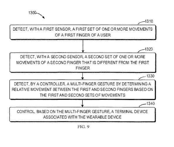
Figure 9 shows a flow chart of the method implemented in the wearable device 100.
At 1320, a second set of one or more movements of the second finger 202 that is different from the first finger 201 is detected with the second sensor 106.
Then, in 1330, through the controller 107, based on the first and second sets of movements, we can determine the relative movement between the first and second fingers 201, 202, thereby realizing a multi-finger gesture. detection.
In 1340, there is a terminal device 300 and a wearable device 100 that are associated with each other through multi-finger gesture control.
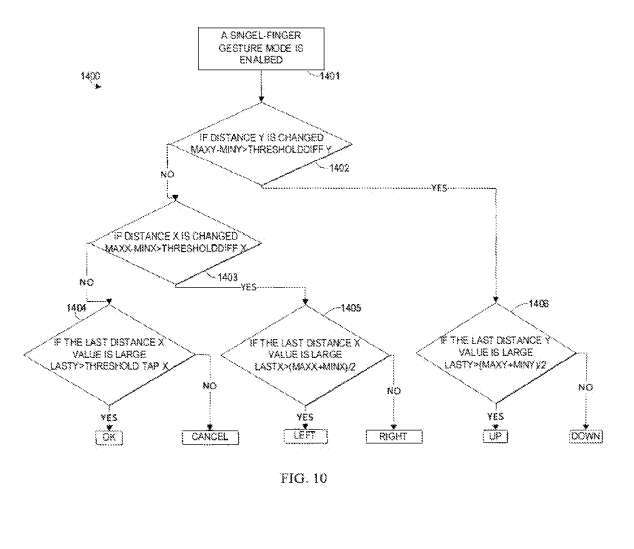
When the wearable device 100 is worn on the index finger, FIG. 10 shows an example of the controller 107 running the recognition algorithm 1400 in the single motion gesture mode.
In 1401, the single motion gesture mode is enabled, and then in 1402, the controller 107 determines whether the distance y302 changes based on the difference between the maximum distance Y and the minimum distance Y being greater than or less than the threshold difference Y, the maximum distance Y Indicates the maximum value detected by the second sensor 106 within a recognition period. Likewise, the minimum distance Y represents the minimum value detected by the second sensor 106 within a recognition period. The maximum distance X refers to the maximum value detected by the first sensor 105 within a recognition cycle, and the minimum distance X refers to the minimum value detected by the first sensor 105 within a recognition cycle.
In 1406, when the distance y302 changes, that is, the difference between the maximum distance Y and the minimum distance Y is greater than the threshold difference Y, then the controller 107 detects the multi-finger gesture by determining whether the final distance Y is large, by determining Whether the final distance Y is greater than the average of the maximum distance Y and the minimum distance Y.
If the final distance Y is greater than the average value, that is, the final distance Y is larger, the controller 107 can detect the multi-finger gesture corresponding to the action set in which the ventral side of the middle section 205 of the index finger 201 moves upward. The controller 107 then triggers the action by generating a control signal corresponding to the "up" operation. On the contrary, if the final distance Y is smaller than the average value, that is, the final distance Y is smaller. In this way, the controller 107 can detect a multi-finger gesture corresponding to a set of movements in which the ventral side of the middle segment 205 of the index finger 201 moves downward. The controller 107 triggers the action by generating a control signal corresponding to the "down" operation.
When the distance y302 remains unchanged, that is, the difference between the maximum distance Y and the minimum distance Y is basically equal to the threshold difference Y, the controller 107 determines whether the difference between the maximum distance X and the minimum distance X is greater than the threshold difference X Whether the distance x301 has changed. Then, the controller 107 determines whether the final distance X is large by determining whether the final distance X is greater than the average value of the maximum distance X and the minimum distance X, thereby detecting the multi-finger gesture.
If the final distance X is greater than the average value, that is, the final distance The controller 107 then triggers action by generating a control signal corresponding to the "left" operation.
If the final distance The controller 107 then triggers action by generating a control signal corresponding to the "right" operation.
Similarly, the multi-action gesture recognition algorithm is also very simple. As mentioned above, special action sets for multi-action gestures can be preset by the user or set manually. The recognition algorithm can then generate a specific control signal by detecting whether a set of movements performed by the user is substantially consistent with a particular movement, and cause the controller 107 to trigger an action.
By using the simplicity of the recognition algorithm and adopting a module based on Bluetooth low energy as the communication module 114, low power consumption of the wearable device 100 can be achieved.
Related Patents: Microsoft Patent | Wearable device enabling multi-finger gestures
The Microsoft patent application titled "Wearable device enabling multi-finger gestures" was originally submitted in August 2023 and was recently published by the US Patent and Trademark Office.
It should be noted that, generally speaking, after a U.S. patent application is reviewed, it will be automatically published 18 months from the filing date or priority date, or it will be published within 18 months from the filing date at the request of the applicant. Note that publication of a patent application does not mean that the patent is approved. After a patent application is filed, the USPTO requires actual review, which can take anywhere from 1 to 3 years.
In addition, this is just a patent application, which does not mean it will be approved. At the same time, it is not sure whether it will be actually commercialized and the actual application effect.
The above is the detailed content of Microsoft patent update reveals a way to operate AR/VR headsets through ring controllers. For more information, please follow other related articles on the PHP Chinese website!
 Else usage in Python loop structure
 A complete list of idea shortcut keys
 Is the success rate of railway 12306 standby ticket high?
 How to hide IP address on TikTok
 What language can vscode be written in?
 How to install printer driver in linux
 How to solve securecrt garbled code
 How about n5095 processor
 How to solve the problem that Win10 folder cannot be deleted


![[Web front-end] Node.js quick start](https://img.php.cn/upload/course/000/000/067/662b5d34ba7c0227.png)