
Optimized object detection and tracking configuration
(英伟网Nweon January 4, 2024) Extended reality devices can detect, track and identify target events or objects through cameras. Traditional tracking systems may not correctly detect user gestures, such as those performed by the user's bare hands or by the user holding an object.
In a patent application titled "Object detection and tracking in extended reality devices", Qualcomm proposed an optimized object detection and tracking configuration.
In one embodiment, the object detection and tracking device may include one or more optical elements and may detect one or more objects or body parts of the user in the virtual environment to identify input gestures performed by the user. Object detection and tracking devices can detect objects in the camera's field of view and determine that the objects correspond to a specific user.
For example, the object detection and tracking device may determine that the object corresponds to the user and is being used to provide an input gesture. The object detection and tracking device may additionally or alternatively determine that the object does not correspond to the user and so will not be used to provide an input gesture.
In another embodiment, the object detection and tracking device may include one or more processors that execute instructions stored in a memory of the object detection and tracking device to perform operations based on the A user's unique silhouette detects the user's object.
For example, the user's unique outline may include one or more shapes characterizing the user's hands, palm prints, palm contours, the size of the user's nails, the shape of the user's nails, the color of the object, etc. The object detection and tracking device may perform instructions for tracking the object based on the user's profile to detect one or more input gestures from the user based on the user's profile.
In one embodiment, the object detection and tracking device may include one or more processors, and the processors perform one or more trained machine learning processes to detect the user's objects to track and receive one or more gesture input.
For example, during the initialization process, the target detection and tracking device may prompt the user to select an object detected by the camera or sensor of the target detection and tracking device as an object for detecting the user's gesture input. The object detection and tracking device may apply the trained machine learning process to the image data characterizing the selected object to generate a plurality of data points of the selected object and a multi-dimensional model of the selected object.
Additionally, target detection and tracking devices can apply trained machine learning processes to multidimensional models of targets to estimate action points. In one example, the object detection and tracking device can implement a training mode for a machine learning process in which the machine learning process can iteratively change the action point in the three-dimensional space of the corresponding gesture.
For example, the target detection and tracking device may determine a gesture based on the generated action points, and may request and receive verification from the user to confirm whether the determined gesture is correct.
One or more processors can apply a machine learning process to the multidimensional model of the object to generate a lookup table. The lookup table may include a list of gestures and a sequence of tracking points in the three-dimensional space that the object may span during the gesture. Tracking points may include x, y, and z coordinates of each tracking point in three-dimensional space.
When the training process is completed, one or more processors may store the values and sequences of tracking points and corresponding gestures as a lookup table in the storage device of the object detection and tracking device. A lookup table corresponding to an object may enable one or more processors to detect and recognize gestures made by the object while tracking the object's motion.
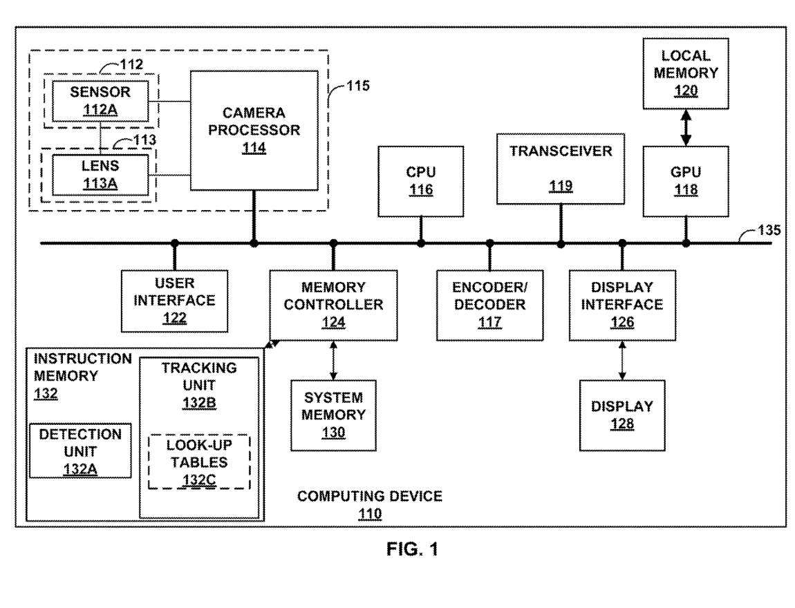
Figure 1 is a block diagram of an exemplary target detection and tracking device 100. As shown in the embodiment of FIG. 1 , target detection and tracking device 100 may include one or more image sensors 112 , such as image sensor 112A, lens 113A, and one or more camera processors, such as camera processor 114 .
The object detection and tracking device 100 may further include a central processing unit 116, an encoder/decoder 117, a graphics processing unit 118, a local memory 120 of the GPU 118, a user interface 122, a system memory 130 and an instruction memory 132. Accessed memory controller 124, and display interface 126.
Object detection and tracking device 100 may receive user input through user interface 122, and in response to the received user input, CPU 116 and/or camera processor 114 may activate the lens corresponding to CPU 116 and/or camera processor. 114. For example, the received user input may correspond to a confirmation that the object/hand seen by lens 113A is the user's object/hand that should be tracked for the input gesture.
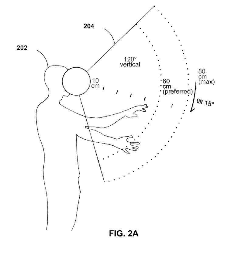
Figure 2A shows the tracking range in the XR system. 2A includes user 202 having field of view 204. As shown in Figure 2A, the user's 202 field of view 204 may have an angular spread of 120 degrees. Field of view 204 may be the area where the VR, AR, or XR system can track user input gestures 202 .
For example, a VR, AR or XR system may track an object, namely the user's hand, within the field of view 204. Field of view 204 may extend from a first radius from the user to a second radius from the user. As shown in Figure 2A, the field of view 204 may extend from a radius of approximately 10 centimeters from the eyes of the user 202 to a radius of 60-80 centimeters from the user.
Although FIG. 2A shows the hand of user 202 in field of view 204, multiple hands of different users may appear in field of view 204. The VR, AR, or XR system can detect hands inserted into the field of view 204, determine whether each hand is associated with a corresponding user, and can track the hands associated with the corresponding user. For example, a VR, AR or XR system can detect input gestures from each user.
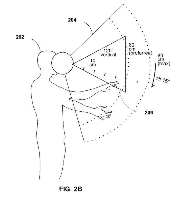
Figure 2B shows the user's field of view 204 with a placement area 206 for initializing target detection and tracking. 2B includes a user 202 having a field of view 204, and a placement area 206 within the field of view 204.
In one embodiment, during initialization of the object detection and tracking process, the object detection and tracking device 100 may generate and display a highlight of the placement area 206 in the virtual environment to the user 202 .
For example, the CPU 116 may execute instructions stored in the detection unit 132A to generate a request for the user 202 to insert an object into the placement area 206. The display unit 208 may cause the placement area 206 to be highlighted in the virtual environment and displayed to the user 202. Upon initialization, the object detection and tracking device 100 may detect objects present in the placement area 206 as objects of the user 202 to be tracked to recognize input gestures from the user 202.
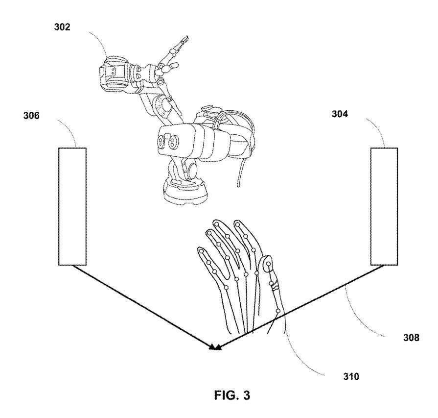
Figure 3 is a diagram illustrating the insertion of an object into the tracking range of the XR system using the object detection and tracking device 100 of Figure 1 . FIG. 3 includes a placement area 308 with the insertion angle and direction of insertion of the user's 202 hand 310 into the placement area 308 highlighted to the user 202 . 3 includes a projection device 302) that can project a placement area 308 surrounded by borders 304 and 306 of the placement area 308.
The projection device 302 may highlight to the user the angle at which the user may insert the hand 310 into the placement area 308 for detection by the object detection and tracking device 100 . In one example, projection device 302 may generate and display an image in the virtual environment that identifies the direction of insertion into placement area 308 and detects hand 310 .
In one embodiment, the target detection and tracking device 100 may determine whether the insertion angle of the hand 310 is within a predetermined range, and may generate outline data identifying the hand 310 as the user's hand based on the determination. For example, the predetermined range may be a range of angle values based on the user's 202 field of view.
When the target detection and tracking device 100 determines that the detection insertion angle of the hand 310 is within a predetermined value range, the target detection and tracking device 100 may register the hand 310 as an object for the user to track. Similarly, the object detection and tracking device 100 may determine that the direction of insertion into the placement area 308 is an appropriate direction (and the object detection and tracking device 100 may register the hand 310 as an object to be tracked for the user.
As another example, the object detection and tracking device 100 may determine that the insertion angle of the hand 310 is not within a predetermined numerical range, and may not associate the hand 310 with the user. Similarly, object detection and tracking device 100 may determine that the direction of insertion into placement area 308 is not an appropriate direction, and may not associate hand 310 with the user.
In this way, the object detection and tracking device 100 may not register the hand 310 as an object to be tracked. In one embodiment, object detection and tracking device 100 may request user 202 to re-enter hand 310 at a suggested angle and/or direction.
For example, object detection and tracking device 100 may provide visual cues through projection within or near placement area 308 to indicate insertion angle and/or insertion direction to user 202 who may then pass the insertion angle and/or insertion direction. The direction inserts hand 310, thereby successfully registering hand 310 as user 202's hand through the XR system.
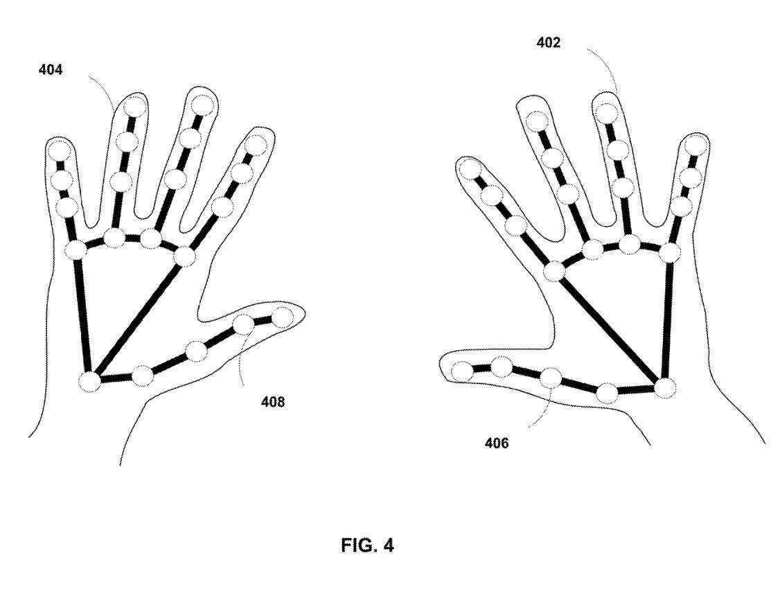
Figure 4 shows the marking technique used to identify hands. Figure 4 includes hands 402 and 404, each of which includes a plurality of landmarks 406 and 408, respectively. Object detection and tracking device 100 may uniquely identify the hand of user 202 as described herein based on landmarks 406 and 408.
For example, each landmark 406 and 408 may be a set of points that uniquely describe the geometry of user 202's hands 402 and 404, respectively. The object detection and tracking device 100 can detect and identify the hands 402 and 404 based on hand line drawings.
Target detection and tracking device 100 may compare landmarks 406 and 408 to a set of points stored in memory of target detection and tracking device 100 . After successfully detecting a match, the object detection and tracking device 100 may determine that the hand inserted into the placement area is the hand of the user 202 and register the detected object as the object of the user 202, thereby tracking and receiving input gestures from the user 202 .
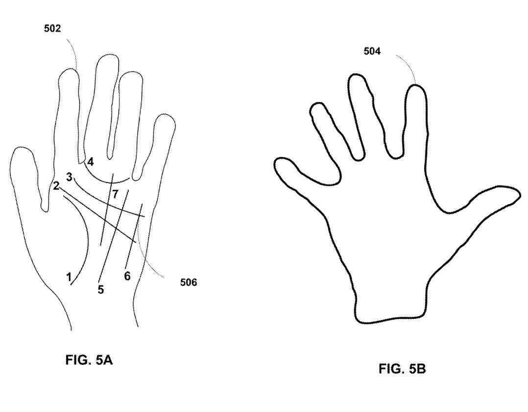
Figure 5A illustrates palm lines that can be used to uniquely identify a hand. As shown in Figure 5A, Figure 5A includes palm print 506 (lines 1-7). The object detection and tracking device 100 may uniquely identify and detect the object having the features shown in FIG. 5A based on comparing the data characterizing the palm line 506 with another set of data characterizing the palm line and stored in the memory of the object detection and tracking device 100 . Palm line of hand.
After determining that the match is successful, the target detection and tracking device 100 can determine the hand inserted into the placement area 308 as the hand of the user 202, and can track the movement of the hand, such as determining the gesture of the user 202. Object detection and tracking device 100 is not limited to utilizing palm line 506 as described above to determine a successful match.
In one embodiment, the object detection and tracking device 100 may utilize other unique characteristics of the user's 202 hand, such as palm contour, hand shape, nail size, nail shape, hand color, etc., to uniquely identify The hand is user 202's hand. Once detected, the object detection and tracking device 100 may generate contour data that registers the hand as that of the user 202 of the XR system. Object detection and tracking device 100 may track hand motion to receive input gestures from user 202 based on the contour data.
Figure 5B shows a palm contour map that can be used to uniquely identify a hand. Figure 5B includes palm outline image data 504 as shown in Figure 5B. Palm profile image data 504 may be based on images captured by camera 115 of object detection and tracking device 100 . Object detection and tracking device 100 may uniquely identify and detect a hand having a palm profile represented by palm profile image data 504 .
For example, the target detection and tracking device 100 may compare the palm profile image data 504 with the palm profile data stored in the memory of the target detection and tracking device 100 to determine whether the palm profile matches.
In one embodiment, system memory 132 stores palm profile data for multiple users. Palm contour data can identify and characterize multiple pixel locations along the contours of the hand captured in the image. Object detection and tracking device 100 may perform operations to determine whether any palm profile data for the user matches the profile of palm profile image data 504 to identify the user.
After determining that the match is successful, the target detection and tracking device 100 can determine the hand inserted into the placement area 308 as the hand of the user 202, and can detect and track the hand gesture as the input gesture of the user 202.
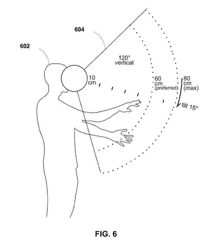
Figure 6 shows the tracking technology in the XR system. Figure 6 includes user 602 having field of view 604. The user's 602 field of view 604 may have an angular extension of several degrees, such as 120 degrees as shown in FIG. 6 . Typically, field of view 604 may be an area in a real environment where a VR, AR, or XR system can track user 602 input gestures.
As shown in Figure 6, the field of view 604 may extend from a radius of approximately 10 cm from the user's 602 eyes to a radius within a range of 60-80 cm from the user.
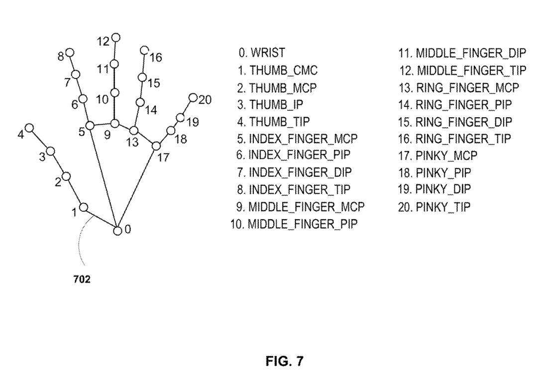
Figure 7 shows a hand tracking diagram using 20 different points of the hand. In it, each of the 20 points is described by their specific position on the common hand. However, when the user's hand has an irregular shape, such as having four fingers instead of five; or the user has a covering on the hand, each of the 20 points shown in Figure 7A may not be exists or cannot be identified.
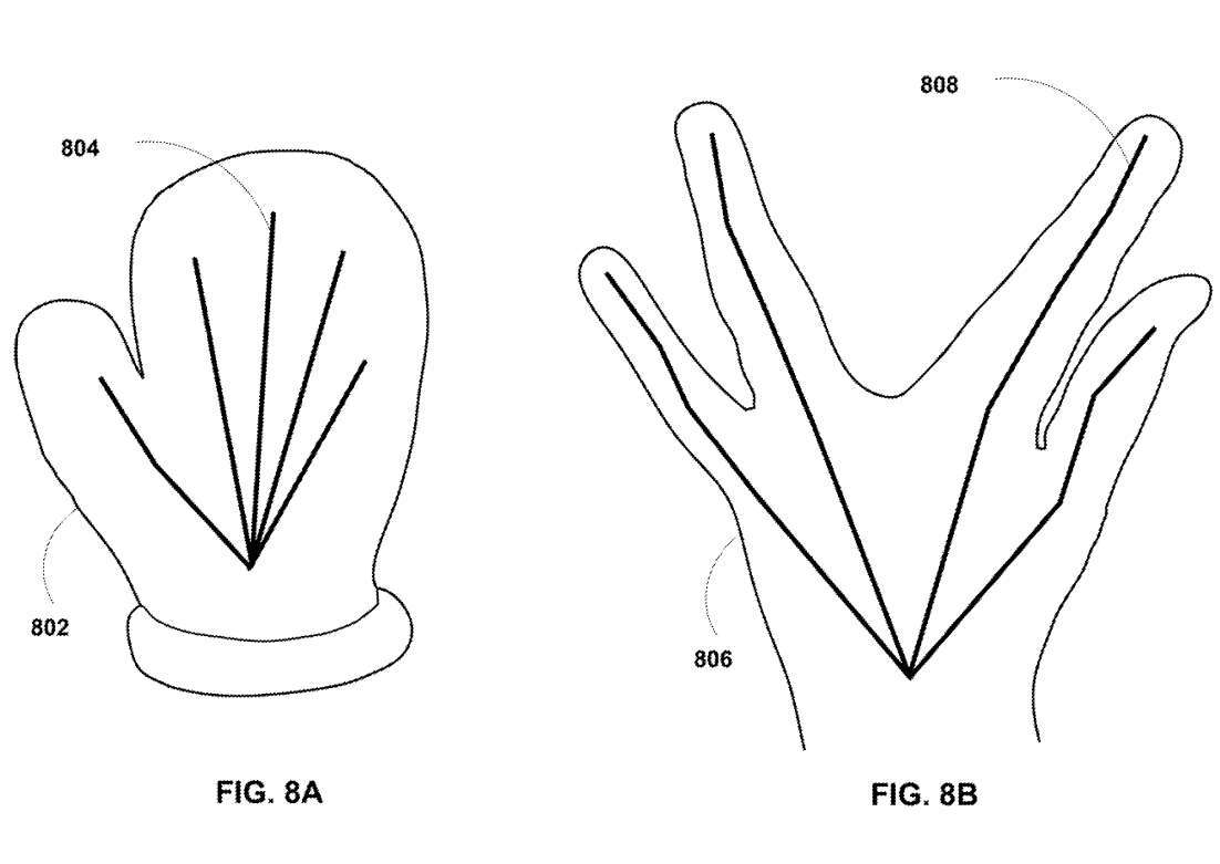
For example, FIG. 8A is a schematic diagram showing a hand with a covering. Figure 8A includes a hand 802 with a mitten covering the hand and an outline 804 representing the shape of the hand 802.
Compared to Figure 7, the 20-point model used to recognize and detect the user's hand may not be used to detect or track the movement of the hand 802 used to recognize the input gesture, at least because the hand 802 cannot be mapped to all 20 points , or map to a sufficient number of points to detect and track the hand 802 using the 20-point technique.
Figure 8B is a schematic diagram showing a hand having an irregular shape. Figure 8B includes a hand 806 having an irregular shape (eg, missing a middle finger), an outline 808 describing the shape of the hand 806. In contrast to Figure 7, the 20-point model used to identify and detect the user's hand may not be used to detect or track the motion of the hand 806 used to recognize the input gesture, at least because the hand 802 may not be mapped to all 20 points, or Map to a sufficient number of points to detect and track the hand 802 using the 20-point technique.
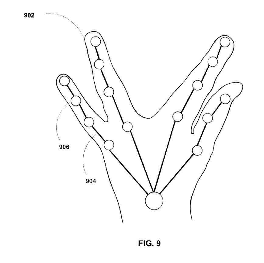
However, the initialization startup technique shown in FIG. 9 may allow the object detection and tracking device 100 to detect unexpected shapes and sizes of objects.
Specifically, Figure 9 illustrates hand tracking techniques for tracking hands with unexpected or irregular shapes. Figure 9 includes hand 902 with contour lines 904. After detecting a covered hand (or a hand with an irregular shape), the object detection and tracking device 100 may generate a plurality of data points 906 for the hand 902 based on the image of the hand 902.
The object detection and tracking device 100 can generate a multi-dimensional model of the hand 902 based on the plurality of data points 906 . For example, the object detection and tracking device 100 may capture one or more images of the hand 902 in a real environment of a hybrid environment of an XR system and plot the data points 906 in three-dimensional space to generate a multi-dimensional model of the hand 902 .
The multi-dimensional model may be a 3D model of the hand 902. The object detection and tracking device 100 may also generate multiple action points based on the multi-dimensional model of the hand 902 and the detected gesture. The object detection and tracking device 100 may further determine a plurality of tracking points.
The tracking point may be a point in the three-dimensional space that the hand 902 is expected to span when making the gesture, and the tracking point may be stored in a lookup table specific to the hand 902. Each sequence of tracking points in the lookup table may correspond to a gesture. As the hand 902 moves in three-dimensional space, the object detection and tracking device 100 may determine the gesture of the hand 902 using a lookup table.
Related Patents: Qualcomm Patent | Object detection and tracking in extended reality devices
https://patent.nweon.com/32609
The Qualcomm patent application titled "Object detection and tracking in extended reality devices" was originally submitted in June 2022 and was recently published by the US Patent and Trademark Office.
It should be noted that, generally speaking, after a U.S. patent application is reviewed, it will be automatically published 18 months from the filing date or priority date, or it will be published within 18 months from the filing date at the request of the applicant. Note that publication of a patent application does not mean that the patent is approved. After a patent application is filed, the USPTO requires actual review, which can take anywhere from 1 to 3 years.
In addition, this is just a patent application, which does not mean it will be approved. At the same time, it is not sure whether it will be actually commercialized and the actual application effect.
---
Original link: https://news.nweon.com/116552
The above is the detailed content of Qualcomm patent proposal to improve object detection and tracking configuration for AR/VR gesture interaction. For more information, please follow other related articles on the PHP Chinese website!


![[Web front-end] Node.js quick start](https://img.php.cn/upload/course/000/000/067/662b5d34ba7c0227.png)