
 Computer Tutorials
Computer Knowledge
Digital audio output interface on the motherboard-SPDIF OUT
Computer Tutorials
Computer Knowledge
Digital audio output interface on the motherboard-SPDIF OUT
Digital audio output interface on the motherboard-SPDIF OUT

SPDIF OUT connection line sequence on the motherboard

Recently I encountered a problem, which is about the wiring sequence of the wires. I checked online, and some information says that 1, 2, and 4 correspond to out, 5V, and ground; while other information says that 1, 2, and 4 correspond to out, ground, and 5V. The best way is to check your motherboard manual. If you can't find the manual, you can use a multimeter to measure it. Find the ground first, then you can determine the order of the rest of the wiring.
How to wire motherboard VDG

When connecting the VDG wiring of the motherboard, you need to plug one end of the VGA cable into the VGA interface of the monitor and the other end into the VGA interface of the computer's graphics card. Please be careful not to plug it into the motherboard's VGA port. After completing the connection, you can turn on the computer for testing. Also, if your computer won't turn on, it may be because your graphics card is missing a driver. You can solve the problem by updating the driver on the Device Manager page or directly downloading the driver from the official website of the graphics card brand. These tips can help you use your computer better.
Motherboard msg interface
MSG is the message indicator light interface on the front panel of the chassis, which is used to display the operating status of the system. When the system is operating normally, the indicator light will remain on; when the system enters standby (s1) mode, the indicator light will flash; and when the system enters hibernation or shutdown state, the indicator light will go out. When connecting, please pay attention to the correct positive and negative polarity.
Most Gigabyte motherboards have a very unique feature, which is the POWERLED indicator light, which is the power light. When we install the chassis, we need to connect the power indicator cable. Generally speaking, there are two types of this cable, one is two-pin type and the other is three-pin type.
How to wire motherboard msg
There is a jumper marked "MSG" on the computer motherboard. It is a message indicator light connected to the power indicator light on the front panel of the chassis. When the system is running, this indicator light will remain on; when the system enters standby (s1) mode, the indicator light will flash; when the system enters sleep or shuts down, the indicator light will go out. When connecting this jumper, you need to pay attention to the positive and negative connections. This jumper is mainly suitable for Gigabyte motherboards.
Related buttons
The operation of the power switch is very simple, you only need to pay attention to two colors and polarity. There are two interfaces on the switch, one is white, representing the positive pole, and the other is brown, representing the negative pole. Regardless of whether it is plugged forward or reversely, just insert the white plug into the positive terminal and the brown plug into the negative terminal, and the power supply will work normally. Therefore, whether it is plugged forward or backward, the power switch can be realized.
The reset switch is a very convenient device that comes in two colors, white and blue. Moreover, whether it is plugged forward or reversely, you can operate it at will. Whether you choose white or blue, whether you plug it in forward or reverse, you can operate it according to your needs. This flexibility makes reset switches very popular. Whether you want to reset the device or adjust the device status, the reset switch can help you do it easily. Whether you use it at home or in the workplace, a reset switch is a very useful tool.
The installation method of the power indicator light is as follows: insert the green plug into the P LED jack and the white plug into the P LED- jack.
Hard disk indicator light: Red is plugged into the "HDD LED", white is plugged into the "HDD LED-" pin.
Speaker: Red plugs into the positive pole, black plugs into the negative pole. According to its working principle, it can be used regardless of the positive and negative poles, just plug it in and use it.
How to wire the motherboard h61h2am3
The components commonly used on the front panel of the chassis include:
The hard disk data indicator light is used to display the status of the hard disk reading data. indicator light. It is usually installed on the computer main case or external hard disk box, and the indicator light will flash or light up when the hard disk reads or writes data. This indicator light is very practical for users to know whether the hard drive is working. Some hard drives will even display different colors according to the speed of reading or writing to more intuitively reflect the status of data reading. By observing the status of the hard disk data indicator, users can keep abreast of the hard disk's read and write activities, thereby better managing and protecting their data.
RESET is a button used to force a restart. It can help us restart the system when there is a problem with the electronic device. Restart buttons are available on various devices, such as mobile phones, computers, game consoles, etc. When the device freezes, freezes, or has other problems, pressing the RESET button can force the device to shut down and restart to solve the problem. The RESET button is usually located on the side or bottom of the device and requires a long, thin object (such as a needle or toothpick) to be pressed lightly for a few seconds until the device turns off. Then press the power button again and the device will restart. It should be noted that some unsaved data may be lost when restarting the device, so it is best to save your work or game progress before pressing the RESET button.
The power indicator light (some are labeled PLED and PLED-) is a device used to indicate the power status. It is usually installed on the front panel or side of an electronic device and is used to show whether the device is working normally or in standby mode. Some power indicators are divided into PLED and PLED—two parts, representing the positive and negative poles respectively. When the device is powered on normally, the power indicator light will light up, indicating that the device is working normally. When the device is in standby mode or not connected to power, the power indicator light will turn off, indicating that the device is in shutdown or standby mode. By observing the status of the power indicator light, we can determine whether the device is working properly and take appropriate measures. For example, if the power indicator light does not light up, it may be that the power supply is faulty or the device is not connected to the power supply. We can check whether the power cord is connected normally, or try to replace the power socket to solve the problem. In short, the power indicator light is very important for our normal use of electronic equipment. It can provide real-time working status information and help us better understand the operation of the equipment.
PWR_BTN (some are labeled PWR and GND separately) Power on button
Just hold a few wires on the chassis in your hand, and then insert them into the corresponding positions according to the pins marked on the motherboard. Complete the connection.
Some USB connector pin headers can be connected directly to the motherboard, while others are separate. For separate pin headers, we need to connect them in a specific order, which is in the order of "power 5V, data -, data, ground GND". We can determine the correct connection sequence according to the identification on the motherboard, just insert the connector into the corresponding position.
There is also a connection pin called F_AUDIO, which is the front audio output and input port. The installation of this connection pin header is very simple, because the socket is already integrated, you only need to align the socket and it can be easily inserted.
The above is the detailed content of Digital audio output interface on the motherboard-SPDIF OUT. For more information, please follow other related articles on the PHP Chinese website!

Hot AI Tools

Undresser.AI Undress
AI-powered app for creating realistic nude photos

AI Clothes Remover
Online AI tool for removing clothes from photos.

Undress AI Tool
Undress images for free

Clothoff.io
AI clothes remover

AI Hentai Generator
Generate AI Hentai for free.

Hot Article
Hot Tools

Notepad++7.3.1
Easy-to-use and free code editor

SublimeText3 Chinese version
Chinese version, very easy to use

Zend Studio 13.0.1
Powerful PHP integrated development environment

Dreamweaver CS6
Visual web development tools

SublimeText3 Mac version
God-level code editing software (SublimeText3)
Hot Topics
 1378
1378
 52
52

 'Valkyrie' joins hands with 'Silver', Biostar displays two Intel Z890 motherboards
Jun 09, 2024 am 11:14 AM
'Valkyrie' joins hands with 'Silver', Biostar displays two Intel Z890 motherboards
Jun 09, 2024 am 11:14 AM
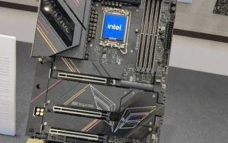
According to news from this website on June 5, according to foreign media TechPowerUp, Biostar exhibited two LGA1851 socket Z890 motherboards supporting Intel's next-generation desktop CPU at the 2024 Taipei International Computer Show. These two motherboards are the flagship Z890VALKYRIE "Valkyrie" and the mainstream Z890A-SILVER. Both are ATX specifications and do not have pre-installed wireless network cards. This website summarizes the detailed parameters of the two motherboards as follows: Z890VALKYRIE continues the gold-powder double-wing elements of the "Valkyrie" family, uses a 23-phase power supply design, and is equipped with 4 DDR5 memory slots. ▲Image source TechPowerUp, the same as below. This motherboard provides 3 alloy-reinforced PCIeG
 Close-up of LGA-1851 socket, Guangji showcases new embedded motherboard: supports Intel Core Ultra 200 series processors
Apr 11, 2024 pm 09:22 PM
Close-up of LGA-1851 socket, Guangji showcases new embedded motherboard: supports Intel Core Ultra 200 series processors
Apr 11, 2024 pm 09:22 PM
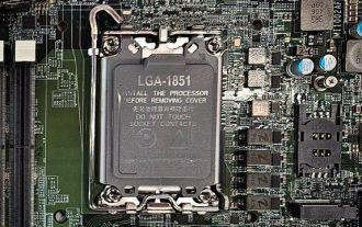
According to the news from this site on April 11, according to the German technology media ComputeBase, Guangji Technology attended the EmbeddedWorld2024 conference and publicly demonstrated a motherboard using the LGA-1851 slot for the first time. This motherboard is compatible with Intel Meteor Lake processors and is mainly used in embedded systems. The media took an in-depth look and shared multiple photos, confirming that LGA-1851 is the same size as Intel’s existing LGA-1700 socket. The relevant pictures attached to this site are as follows: Not compatible with CPU, but compatible with CPU coolers but not LGA-1851 socket 151 additional pins were added and the CPU locking system was adjusted, so it is not compatible with existing LGA-1700 socket processors. But because LG
 Sapphire launches NITRO+ B650I WIFI ultra-platinum motherboard, 1679 yuan
Apr 22, 2024 pm 01:58 PM
Sapphire launches NITRO+ B650I WIFI ultra-platinum motherboard, 1679 yuan
Apr 22, 2024 pm 01:58 PM
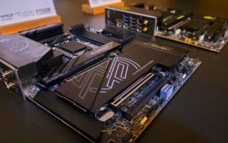
According to news from this site on April 22, Sapphire (Sapphire Technology) recently launched the NITRO+B650IWIFI ultra-platinum motherboard. The e-commerce platform sells it for 1,689 yuan. You can get a 10 yuan coupon, and the price is 1,679 yuan. According to inquiries on this site, Sapphire released a NITRO+B550I motherboard in 2021, and this new product can be regarded as the successor of that product. Sapphire NITRO+B650IWIFI adopts 8-layer PCB+8-phase digital power supply design, uses PowerStage70ADr.MOS, and supports DDR5-6000+ memory overclocking. In terms of storage, it is equipped with 2 Gen4x4 M.2 interfaces and 4 SATA3 interfaces. This motherboard is covered with MOS power supply and front M.2 bay.
 'The world's first Thin Mini ITX motherboard supporting AM5', ASRock releases X600TM-ITX: up to 96GB memory, 4 external monitors
Jul 27, 2024 am 10:37 AM
'The world's first Thin Mini ITX motherboard supporting AM5', ASRock releases X600TM-ITX: up to 96GB memory, 4 external monitors
Jul 27, 2024 am 10:37 AM
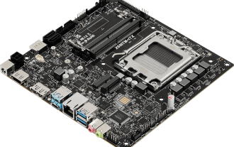
According to news from this site on July 27, ASRock recently announced the launch of the X600TM-ITX motherboard, claiming to be "the world's first ThinMiniITX motherboard that supports AM5". The motherboard size is 17*17 cm and supports AMD Ryzen 9000/8000/7000 series processing. device. ASRock said that this motherboard is suitable for products such as mini computers, all-in-one computers, smart mirrors, educational tools, and home theater computers, and can handle various tasks in daily offices, presentations, and work. X600TM-ITX supports the latest AM5 processor, which improves performance by up to 1.33 times compared to the previous generation. This means faster speeds, increased multitasking capabilities, better gaming experiences, faster data processing, and
 ASUS releases BIOS update for Z790 motherboards to alleviate instability issues with Intel's 13th/14th generation Core processors
Aug 09, 2024 am 12:47 AM
ASUS releases BIOS update for Z790 motherboards to alleviate instability issues with Intel's 13th/14th generation Core processors
Aug 09, 2024 am 12:47 AM
According to news from this website on August 8, MSI and ASUS today launched a beta version of BIOS containing the 0x129 microcode update for some Z790 motherboards in response to the instability issues in Intel Core 13th and 14th generation desktop processors. ASUS's first batch of motherboards to provide BIOS updates include: ROGMAXIMUSZ790HEROBetaBios2503ROGMAXIMUSZ790DARKHEROBetaBios1503ROGMAXIMUSZ790HEROBTFBetaBios1503ROGMAXIMUSZ790HEROEVA-02 joint version BetaBios2503ROGMAXIMUSZ790A
 Supporting the new generation of CAMM2 memory modules, MSI and ASRock exhibited special Intel motherboards
Jun 07, 2024 am 11:23 AM
Supporting the new generation of CAMM2 memory modules, MSI and ASRock exhibited special Intel motherboards
Jun 07, 2024 am 11:23 AM
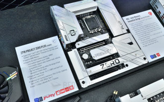
According to news from this site on June 4, based on reports from Taiwanese media BenchLife.info and updates from X platform user @wagipon, both MSI and ASRock exhibited special Intel motherboards that support CAMM2 memory modules at the 2024 Taipei International Computer Show. Among them, MSI brought the previously warmed-up Z790PROJECTZEROPLUS (CAMM2) motherboard, which is equipped with the FURYImpactDDR5CAMM2 prototype memory module from Kingston. ▲Picture source BenchLife.info MSI stated that the DDR5CAMM2 memory module can support up to 128GB capacity, and a single module can achieve dual channels, which can reduce compatibility issues (Note from this site: Even if only the batch number is different, the traditional
 MSI MPG X870E CARBON WiFi motherboard appears at Gamescom 2024, equipped with dual wired network ports
Aug 22, 2024 am 11:36 AM
MSI MPG X870E CARBON WiFi motherboard appears at Gamescom 2024, equipped with dual wired network ports
Aug 22, 2024 am 11:36 AM
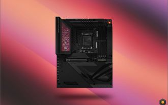
According to news from this website on August 22, according to Spanish media GEEKNETIC, MSI exhibited the MPGX870ECARBON WiFi motherboard at the gamesom2024 Cologne game show. ▲Image source GEEKNETIC, the same below MPGX870ECARBONWiFi is also the third new generation AMD800 series motherboard displayed by MSI. The first two models MAGX870TOMAHAWKWIFI and PROX870-PWIFI have been introduced in previous articles on this site. MSI MPGX870ECARBONWiFi motherboard adopts ATX form factor, 18+2+1 phase power supply design, equipped with 110ASPSDr.MOS, and has 4 DDR5
 Colorful launches CVN B650M GAMING FROZEN motherboard: supports AMD Ryzen 8000 series processors
Mar 28, 2024 pm 03:17 PM
Colorful launches CVN B650M GAMING FROZEN motherboard: supports AMD Ryzen 8000 series processors
Mar 28, 2024 pm 03:17 PM
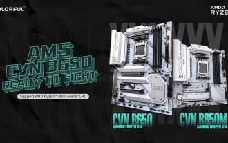
According to news from this website on March 28, Colorful recently launched the CVNB650MGAMINGFROZEN motherboard, which the official claims is the brand’s first AMDAM5 motherboard to support the AMD Ryzen7000 series and the latest Ryzen8000 series. The CVNB650MGAMINGFROZEN motherboard supports AMD's latest Ryzen8000G series APU, supports the AMD Ryzen7000 series of AMD Ryzen7000X3D series processors that have adopted 3DV-Cache technology, and supports the subsequent launch of AM5 processors. CVNB650MGAMINGFROZEN adopts 12+1+1 digital power phase design and is equipped with 55ADrMo
