

Warning! Long-distance LiDAR sensing

1. Introduction
After the Tucson AI Day was held last year, I always had the idea to summarize our work in long-distance perception in text form. I happened to have some time recently, so I decided to write an article to record the research process in the past few years. The content covered in this article can be found in the Tucson AI Day video [0] and our publicly published papers, but it does not contain specific engineering details or technical secrets.
As we all know, Tucson focuses on autonomous truck driving technology. Trucks have longer braking distances and longer lane changes than cars. As a result, Tucson has a unique advantage in competing with other autonomous driving companies. As a member of Tucson, I am responsible for LiDAR sensing technology, and now I will introduce in detail the related content of using LiDAR for long-distance sensing.
When the company first joined, the mainstream LiDAR sensing solution was usually the BEV (Bird's Eye View) solution. However, the BEV here is not the abbreviation of the well-known Battery Electric Vehicle, but refers to a solution that projects LiDAR point clouds into the BEV space and combines 2D convolution and 2D detection heads for target detection. I personally think that the LiDAR sensing technology used by Tesla should be called "the fusion technology of multi-view cameras in the BEV space." As far as I can tell, the earliest record of the BEV solution is the paper "MV3D" published by Baidu at the CVPR17 conference [1]. Many subsequent research works, including the solutions actually used by many companies that I know, adopt the method of projecting LiDAR point clouds into the BEV space for target detection, and can be classified as BEV solutions. This solution is widely used in practical applications. To summarize, when I first joined the company, the mainstream LiDAR sensing solution usually projected the LiDAR point cloud into the BEV space, and then combined 2D convolution and a 2D detection head for target detection. The LiDAR sensing technology used by Tesla can be called "the fusion technology of multi-view cameras in the BEV space." The paper "MV3D" published by Baidu at the CVPR17 conference was an early record of the BEV solution. Subsequently, many companies also adopted similar solutions for target detection.
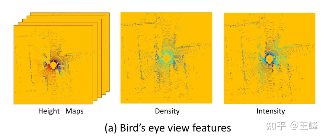 The BEV perspective feature used by MV3D[1]
One of the great benefits of the BEV scheme is that it can directly apply mature 2D detectors, but it also has a fatal shortcoming: it limits Covered the range of perception. As you can see from the picture above, because a 2D detector is to be used, it must form a 2D feature map. At this time, a distance threshold must be set for it. In fact, there are still LiDAR points outside the range of the picture above, but was discarded by this truncation operation. Is it possible to increase the distance threshold until the location is covered? It's not impossible to do this, but LiDAR has very few point clouds in the distance due to problems such as scanning mode, reflection intensity (attenuating with distance to the fourth power), occlusion, etc., so it is not cost-effective.
The academic community has not paid much attention to this issue of the BEV scheme, mainly due to the limitations of the data set. The annotation range of current mainstream data sets is usually less than 80 meters (such as nuScenes' 50 meters, KITTI's 70 meters and Waymo's 80 meters). Within this distance range, the size of the BEV feature map does not need to be large. However, in the industrial world, the mid-range LiDAR used can generally achieve a scanning range of 200 meters, and in recent years, some long-range LiDARs have been released, which can achieve a scanning range of 500 meters. It should be noted that the area and calculation amount of the feature map increase quadratically as the distance increases. Under the BEV scheme, the amount of calculation required to handle a range of 200 meters is already considerable, let alone a range of 500 meters. Therefore, this problem needs more attention and resolution in the industry.
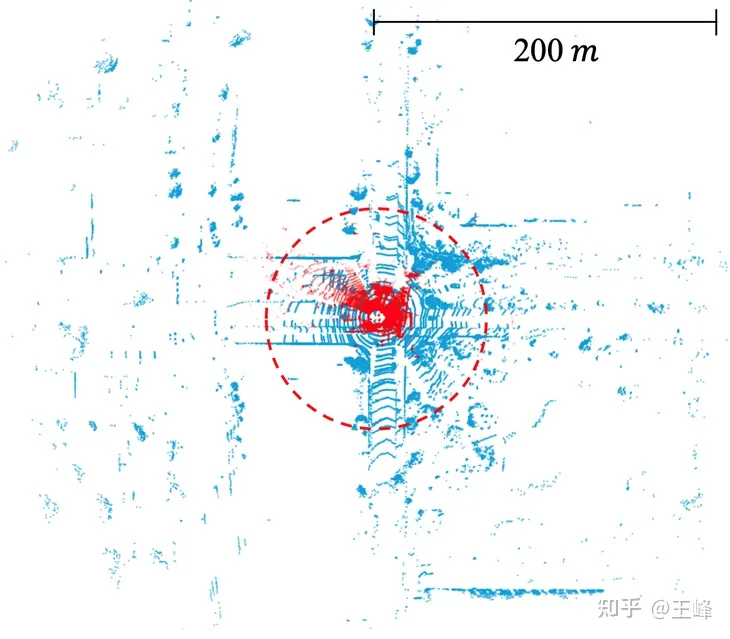
The scanning range of lidar in the public data set. KITTI (red dot, 70m) vs. Argoverse 2 (blue dot, 200m)
After recognizing the limitations of the BEV solution, we finally found a feasible alternative after years of research. The research process was not easy and we experienced many setbacks. Generally, papers and reports will only emphasize successes and not mention failures, but the experience of failure is also very valuable. Therefore, we decided to share our research journey through a blog. Next, I will describe it step by step according to the timeline.
2. Point-based solution
At CVPR19, Hong Kong Chinese published a point cloud detector called PointRCNN[2]. Unlike traditional methods, PointRCNN performs calculations directly on point cloud data without converting it to BEV (bird's eye view) form. Therefore, this point cloud-based solution can theoretically achieve long-distance sensing.
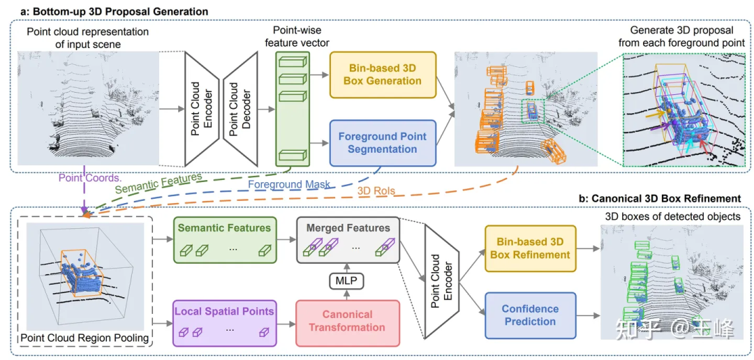
But we found a problem after trying it. The number of point clouds in one frame of KITTI can be downsampled to 16,000 points for detection without much loss of points. However, our LiDAR combination has more than 100,000 points in one frame. If Downsampling by 10 times will obviously greatly affect the detection accuracy. If downsampling is not performed, there are even O(n^2) operations in the backbone of PointRCNN. As a result, although it does not take bev, the calculation amount is still unbearable. These time-consuming operations are mainly due to the disordered nature of the point cloud itself, which means that all points must be traversed whether downsampling or neighborhood retrieval. Since there are many ops involved and they are all standard ops that have not been optimized, there is no hope of optimizing to real-time in the short term, so this route was abandoned.
However, this research is not wasted. Although the calculation amount of backbone is too large, its second stage is only performed on the foreground, so the calculation amount is still relatively small. After directly applying the second stage of PointRCNN to the first stage detector of the BEV scheme, the accuracy of the detection frame will be greatly improved. During the application process, we also discovered a small problem with it. After solving it, we summarized it and published it in an article [3] published on CVPR21. You can also check it out on this blog:
王峰: LiDAR R-CNN: A fast and versatile two-stage 3D detector
3. Range-View scheme
After the Point-based scheme failed, We turned our attention to Range View. LiDARs back then were all mechanically rotating. For example, a 64-line lidar would scan 64 rows of point clouds with different pitch angles. For example, if each row scanned 2048 points, it would be enough. Form a 64*2048 range image.
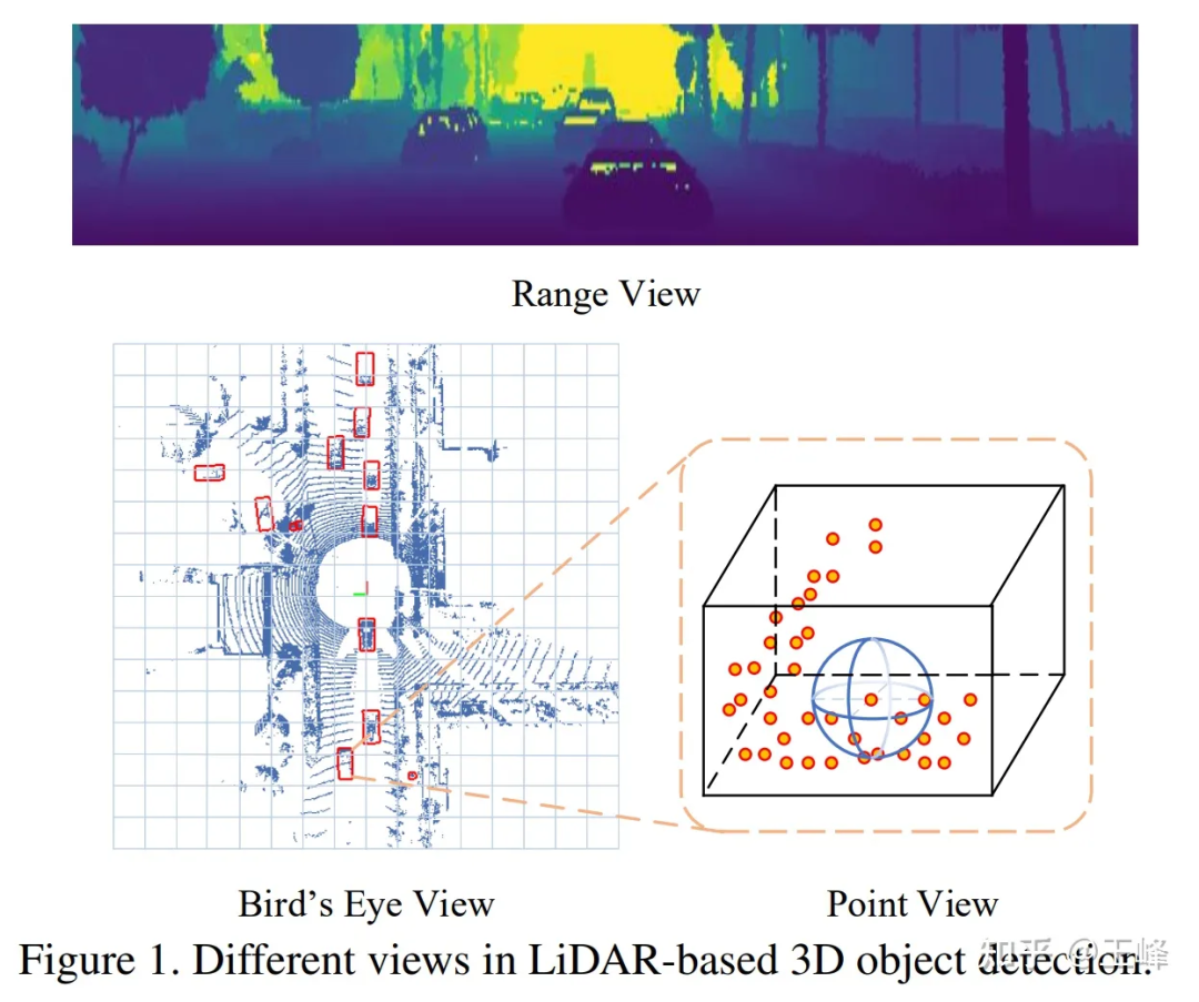 Comparison of RV, BEV, and PV
In Range View, the point cloud is no longer sparse but densely arranged together, and distant targets are in the range image The upper part is relatively small, but it will not be discarded, so it can theoretically be detected.
Maybe because it is more similar to the image, the research on RV is actually earlier than BEV. The earliest record I can find is also from Baidu’s paper [4]. Baidu is really the Whampoa Military Academy of autonomous driving. , the earliest applications of both RV and BEV came from Baidu.
So I tried it out casually. Compared with the BEV method, RV’s AP dropped by 30-40 points... I found that the detection on the 2d range image was actually pretty good. But the effect of the output 3D frame is very poor. At that time, when we analyzed the characteristics of RV, we felt that it had all the disadvantages of images: non-uniform object scales, mixed foreground and background features, and unclear long-distance target features. However, it did not have the advantage of rich semantic features in images, so I was relatively pessimistic about this solution at the time.
Because regular employees still have to do the implementation work after all, it is better to leave such exploratory questions to interns. Later, two interns were recruited to study this problem together. They tried it on the public data set, and sure enough, they also lost 30 points... Fortunately, the two interns were more capable. Through a series of efforts and reference to other After correcting some details of the paper, the points were brought to a level similar to the mainstream BEV method, and the final paper was published on ICCV21 [5].
Although the points are increased, the problem has not been completely solved. At that time, it has become a consensus that lidar needs multi-frame fusion to improve the signal-to-noise ratio. Because the points are small for long-distance targets, it is even more necessary to stack frames to increase the number of points. amount of information. In the BEV solution, multi-frame fusion is very simple. Just add a timestamp to the input point cloud and then superimpose multiple frames. The entire network can increase the points without changing it. However, under RV, many tricks have been changed and nothing has been achieved. Similar effect.
And at this time, LiDAR has also moved from mechanical rotation to solid/semi-solid in terms of hardware technical solutions. Most solid/semi-solid LiDAR can no longer form a range image and forcibly construct a range. image will lose information, so this path was eventually abandoned.
4. Sparse Voxel scheme
As mentioned before, the problem with the Point-based scheme is that the irregular arrangement of point clouds requires traversal for issues such as downsampling and neighborhood retrieval. All point clouds result in too high a computational burden, while under the BEV scheme the data is organized but there are too many blank areas, resulting in an excessively high computational burden. Combining the two, performing voxelization in dotted areas to make it regular, and not expressing in undotted areas to prevent invalid calculations seems to be a feasible path. This is the sparse voxel solution.
Because Yan Yan, the author of SECOND[6], joined Tucson, we tried the backbone of sparse conv in the early days. However, because spconv is not a standard op, the spconv implemented by ourselves still passed Slow enough to detect in real time, sometimes even slower than dense conv, so it was put aside for the time being.
Later, the first LiDAR capable of scanning 500m: Livox Tele15 arrived, and the long-range LiDAR sensing algorithm was imminent. I tried the BEV solution but it was too expensive, so I tried the spconv solution again. For a moment, because the fov of Tele15 is relatively narrow and the point cloud in the distance is also very sparse, spconv can barely achieve real-time performance.
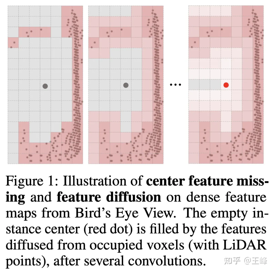
But if you don’t shoot bev, the detection head cannot use the more mature anchor or center assign in 2D detection. This is mainly because the lidar scans the surface of the object, and the center position is not necessarily a point (as shown in the figure below) (shown), it is naturally impossible to assign a foreground target without a point. In fact, we have tried many assign methods internally. We will not go into details about the actual methods used by the company here. The intern also tried an assign scheme and published it on NIPS2022 [7]. You can read his interpretation. :
明月不知无愿:Fully Sparse 3D Object Detector
But if you want to apply this algorithm 500m forward, backward and With the LiDAR combination of 150m on the left and right, it is still insufficient. It just so happened that the intern used to draw on the ideas of Swin Transformer and wrote an article on Sparse Transformer before chasing popularity [8]. It also took a lot of effort to brush up from more than 20 points bit by bit (thanks to the intern for guiding me, tql ). At that time, I felt that the Transformer method was still very suitable for irregular point cloud data, so I also tried it on the company's data set.
Unfortunately, this method has always failed to beat the BEV method on the company's data set, and the difference is close to 5 points. Looking back now, there may still be some tricks or training techniques that I have not mastered. It stands to reason that Transformer The expressive ability is not weaker than conv, but I did not continue to try it later. However, at this time, the assign method has been optimized and reduced a lot of calculations, so I wanted to try spconv again. The surprising result is that directly replacing the Transformer with spconv can achieve the same accuracy as the BEV method at close range. Quite, it can also detect long-distance targets.
It was also at this time that Yan Yan made the second version of spconv[9]. The speed was greatly improved, so computing delay was no longer a bottleneck. Finally, long-distance LiDAR perception cleared everything Obstacles can now be run on the car in real time.
Later, we updated the LiDAR arrangement and increased the scanning range to 500m forward, 300m backward, and 150m left and right. This algorithm also runs well. I believe that with the continuous improvement of computing power in the future , computing latency will become less and less of a problem.
The final long-distance detection effect is shown below. You can also look at the position around 01:08:30 in the Tucson ai day video to see the dynamic detection effect:
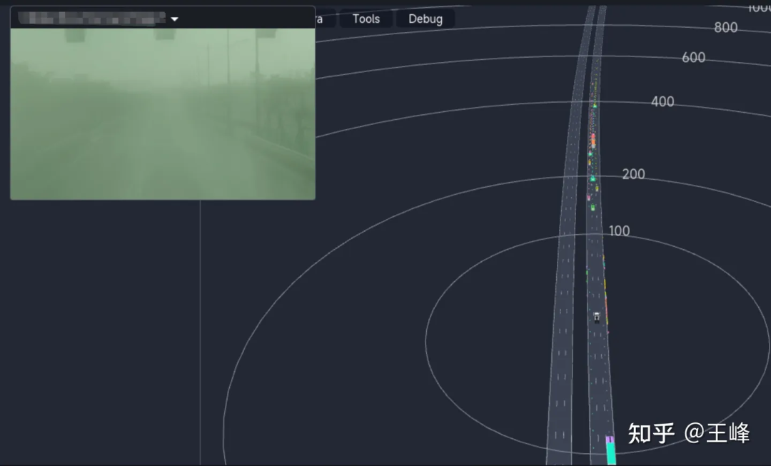
Although it is the final fusion result, because the visibility of the foggy image on this day is very low, the results basically come from LiDAR perception.
5. Postscript
From the point-based method, to the range image method, to the Transformer and sparse conv methods based on sparse voxel, the exploration of long-distance perception It cannot be said that it was smooth sailing, it was simply a road full of thorns. In the end, it was actually with the continuous improvement of computing power and the continuous efforts of many colleagues that we achieved this step. I would like to thank Tucson chief scientist Wang Naiyan and all colleagues and interns in Tucson. Most of the ideas and engineering implementations were not done by me. I am very ashamed. They serve more as a link between the past and the future.
I haven’t written such a long article for a long time. It was written like a running account without forming a touching story. In recent years, fewer and fewer colleagues insist on doing L4, and L2 colleagues have gradually turned to purely visual research. LiDAR perception is gradually marginalized visibly to the naked eye, although I still firmly believe that one more direct ranging sensor is better. choice, but industry insiders seem to increasingly disagree. As I see more and more BEV and Occupancy on the resumes of the fresh blood, I wonder how long LiDAR sensing can continue, and how long I can persist. Writing such an article may also serve as a commemoration.
I’m in tears late at night, I don’t understand what I’m talking about, I’m sorry.
The above is the detailed content of Warning! Long-distance LiDAR sensing. For more information, please follow other related articles on the PHP Chinese website!

Hot AI Tools

Undresser.AI Undress
AI-powered app for creating realistic nude photos

AI Clothes Remover
Online AI tool for removing clothes from photos.

Undress AI Tool
Undress images for free

Clothoff.io
AI clothes remover

Video Face Swap
Swap faces in any video effortlessly with our completely free AI face swap tool!

Hot Article
Hot Tools

Notepad++7.3.1
Easy-to-use and free code editor

SublimeText3 Chinese version
Chinese version, very easy to use

Zend Studio 13.0.1
Powerful PHP integrated development environment

Dreamweaver CS6
Visual web development tools

SublimeText3 Mac version
God-level code editing software (SublimeText3)
Hot Topics
 1386
1386
 52
52

 What are the top ten virtual currency trading platforms? Ranking of the top ten virtual currency trading platforms in the world
Feb 20, 2025 pm 02:15 PM
What are the top ten virtual currency trading platforms? Ranking of the top ten virtual currency trading platforms in the world
Feb 20, 2025 pm 02:15 PM
With the popularity of cryptocurrencies, virtual currency trading platforms have emerged. The top ten virtual currency trading platforms in the world are ranked as follows according to transaction volume and market share: Binance, Coinbase, FTX, KuCoin, Crypto.com, Kraken, Huobi, Gate.io, Bitfinex, Gemini. These platforms offer a wide range of services, ranging from a wide range of cryptocurrency choices to derivatives trading, suitable for traders of varying levels.
 Do I need to use flexbox in the center of the Bootstrap picture?
Apr 07, 2025 am 09:06 AM
Do I need to use flexbox in the center of the Bootstrap picture?
Apr 07, 2025 am 09:06 AM
There are many ways to center Bootstrap pictures, and you don’t have to use Flexbox. If you only need to center horizontally, the text-center class is enough; if you need to center vertically or multiple elements, Flexbox or Grid is more suitable. Flexbox is less compatible and may increase complexity, while Grid is more powerful and has a higher learning cost. When choosing a method, you should weigh the pros and cons and choose the most suitable method according to your needs and preferences.
 How to adjust Sesame Open Exchange into Chinese
Mar 04, 2025 pm 11:51 PM
How to adjust Sesame Open Exchange into Chinese
Mar 04, 2025 pm 11:51 PM
How to adjust Sesame Open Exchange to Chinese? This tutorial covers detailed steps on computers and Android mobile phones, from preliminary preparation to operational processes, and then to solving common problems, helping you easily switch the Sesame Open Exchange interface to Chinese and quickly get started with the trading platform.
 Top 10 cryptocurrency trading platforms, top ten recommended currency trading platform apps
Mar 17, 2025 pm 06:03 PM
Top 10 cryptocurrency trading platforms, top ten recommended currency trading platform apps
Mar 17, 2025 pm 06:03 PM
The top ten cryptocurrency trading platforms include: 1. OKX, 2. Binance, 3. Gate.io, 4. Kraken, 5. Huobi, 6. Coinbase, 7. KuCoin, 8. Crypto.com, 9. Bitfinex, 10. Gemini. Security, liquidity, handling fees, currency selection, user interface and customer support should be considered when choosing a platform.
 How to calculate c-subscript 3 subscript 5 c-subscript 3 subscript 5 algorithm tutorial
Apr 03, 2025 pm 10:33 PM
How to calculate c-subscript 3 subscript 5 c-subscript 3 subscript 5 algorithm tutorial
Apr 03, 2025 pm 10:33 PM
The calculation of C35 is essentially combinatorial mathematics, representing the number of combinations selected from 3 of 5 elements. The calculation formula is C53 = 5! / (3! * 2!), which can be directly calculated by loops to improve efficiency and avoid overflow. In addition, understanding the nature of combinations and mastering efficient calculation methods is crucial to solving many problems in the fields of probability statistics, cryptography, algorithm design, etc.
 Top 10 virtual currency trading platforms 2025 cryptocurrency trading apps ranking top ten
Mar 17, 2025 pm 05:54 PM
Top 10 virtual currency trading platforms 2025 cryptocurrency trading apps ranking top ten
Mar 17, 2025 pm 05:54 PM
Top Ten Virtual Currency Trading Platforms 2025: 1. OKX, 2. Binance, 3. Gate.io, 4. Kraken, 5. Huobi, 6. Coinbase, 7. KuCoin, 8. Crypto.com, 9. Bitfinex, 10. Gemini. Security, liquidity, handling fees, currency selection, user interface and customer support should be considered when choosing a platform.
 What are the safe and reliable digital currency platforms?
Mar 17, 2025 pm 05:42 PM
What are the safe and reliable digital currency platforms?
Mar 17, 2025 pm 05:42 PM
A safe and reliable digital currency platform: 1. OKX, 2. Binance, 3. Gate.io, 4. Kraken, 5. Huobi, 6. Coinbase, 7. KuCoin, 8. Crypto.com, 9. Bitfinex, 10. Gemini. Security, liquidity, handling fees, currency selection, user interface and customer support should be considered when choosing a platform.
 Recommended safe virtual currency software apps Top 10 digital currency trading apps ranking 2025
Mar 17, 2025 pm 05:48 PM
Recommended safe virtual currency software apps Top 10 digital currency trading apps ranking 2025
Mar 17, 2025 pm 05:48 PM
Recommended safe virtual currency software apps: 1. OKX, 2. Binance, 3. Gate.io, 4. Kraken, 5. Huobi, 6. Coinbase, 7. KuCoin, 8. Crypto.com, 9. Bitfinex, 10. Gemini. Security, liquidity, handling fees, currency selection, user interface and customer support should be considered when choosing a platform.
