
 Software Tutorial
Computer Software
Graphical and textual methods for UG modeling of turning parts
Software Tutorial
Computer Software
Graphical and textual methods for UG modeling of turning parts
Graphical and textual methods for UG modeling of turning parts

php Xiaobian Zimo will introduce to you the graphic method of UG modeling turning parts. UG is a professional three-dimensional modeling software suitable for manufacturing design and development. Through this article, we will introduce you in detail how to model turning parts in UG software, so that you can master the process and skills of making parts. By studying the content of this article, you will be able to use UG software for modeling more skillfully and improve modeling efficiency and quality. Let’s learn about the graphic and textual methods of UG modeling turned parts!
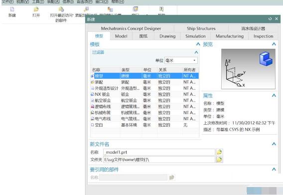
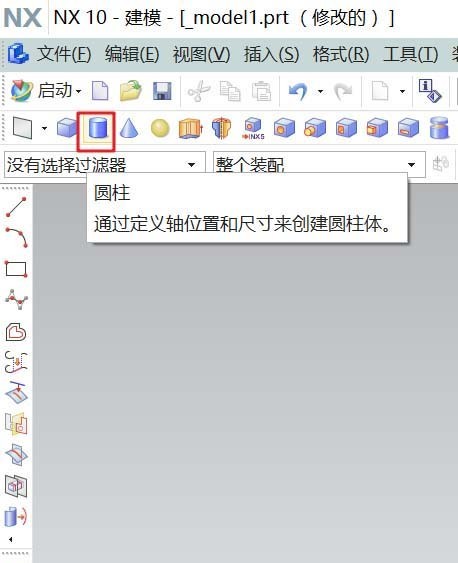
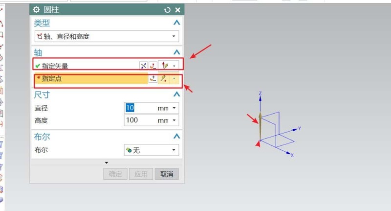
1. Open UG10.0 and create a new modeling file. Select cylinder in the shortcut menu bar, specify the vector direction for the cylinder, determine the center point, and set the parameters of the cylinder. After confirming, you can get a cylinder. This cylinder is the base of the workpiece. Other structures are created on top of it.
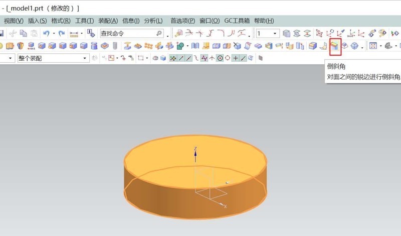
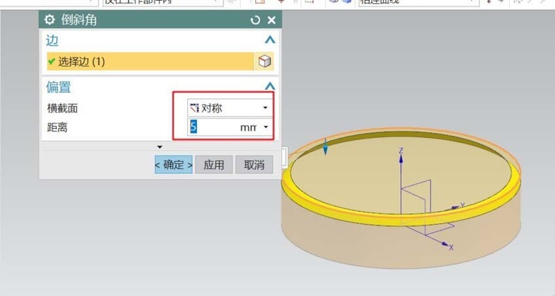
#2. Select [Chamfer] to chamfer the symmetrical angle on the top of the cylinder: 5. This step can also be done together with the final adjustments to the details.
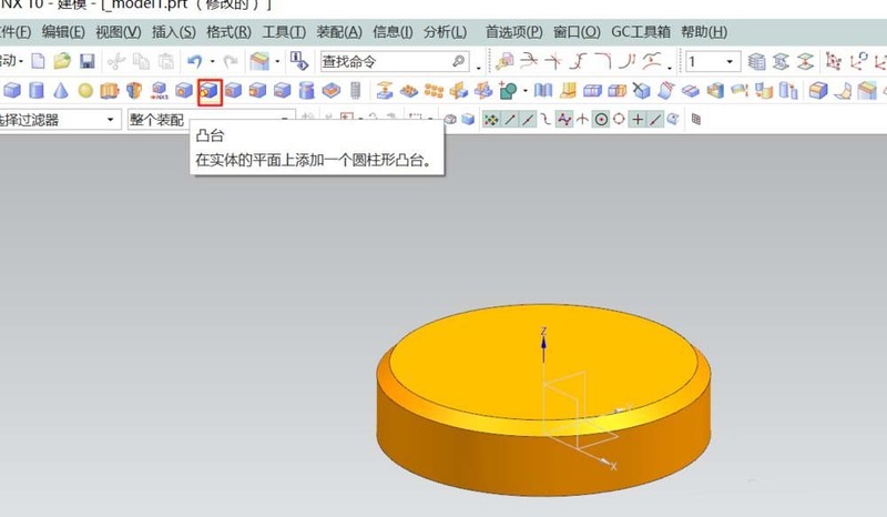
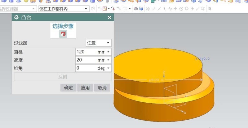
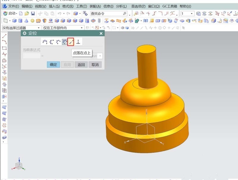
3. Select the [Boss] command and set the parameters of the boss placement surface in the pop-up dialog box: diameter: 120; height: 20. In the final positioning, select point to point and select the top center of the basic cylinder. The second boss is also completed in the same way, but the surface it is placed on is the top of the previous boss.
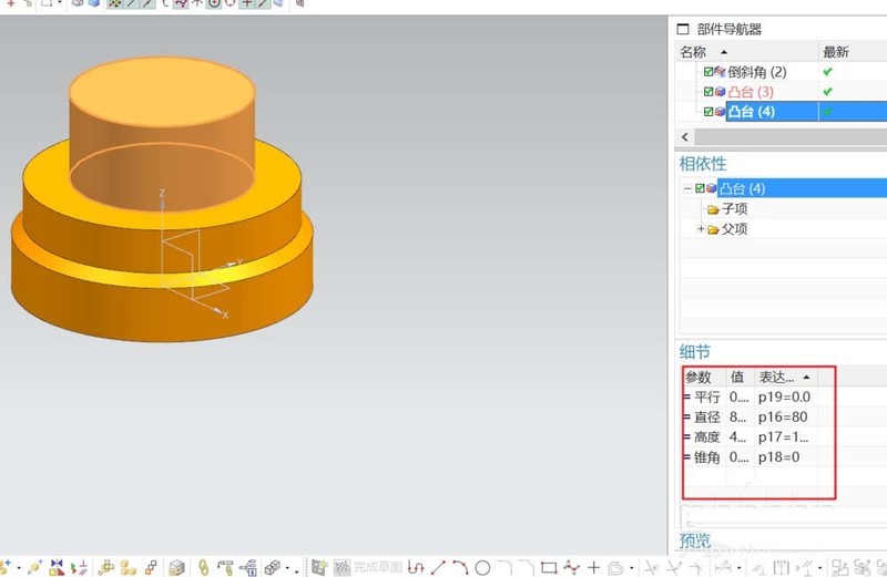
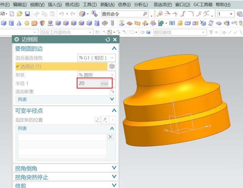
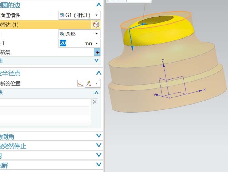
#4. Round the second boss with a radius of 20 on both sides.
#5. Add two more bosses on the top surface of the rounded corner to finally complete the basic shape of the workpiece.
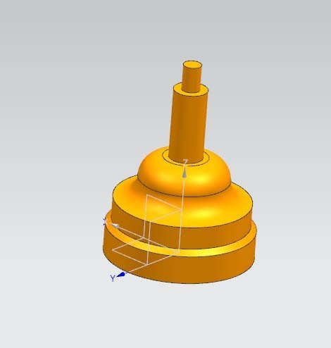
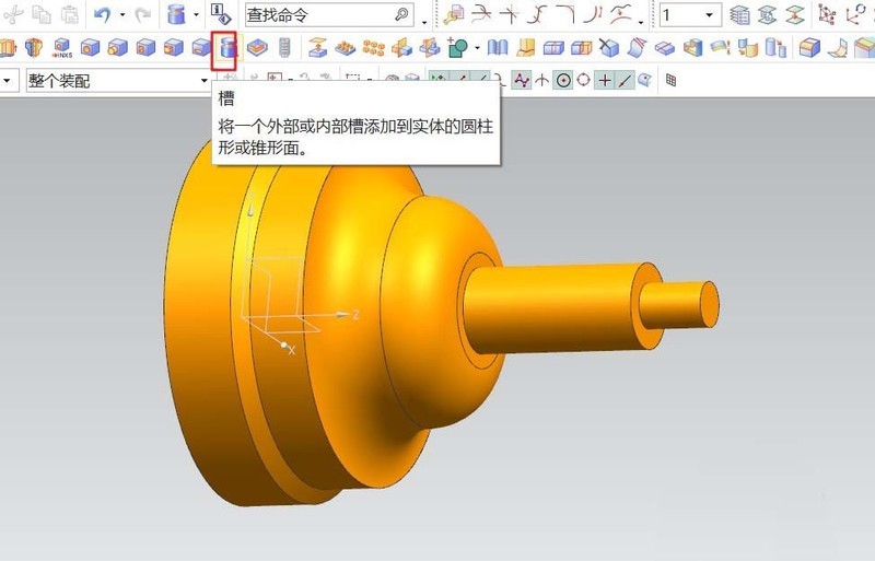
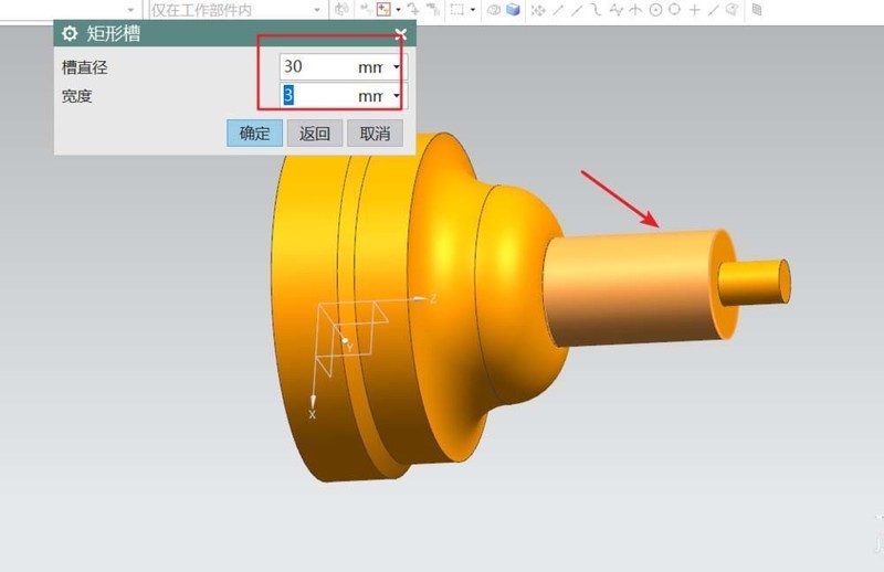
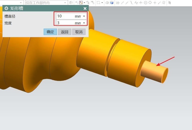
#6. Adjustment of workpiece details. Add grooves to the workpiece and add undercut grooves to the two uppermost bosses. Finally, chamfer the sharp edges. The end result is a turned workpiece.
The above is the detailed content of Graphical and textual methods for UG modeling of turning parts. For more information, please follow other related articles on the PHP Chinese website!

Hot AI Tools

Undresser.AI Undress
AI-powered app for creating realistic nude photos

AI Clothes Remover
Online AI tool for removing clothes from photos.

Undress AI Tool
Undress images for free

Clothoff.io
AI clothes remover

AI Hentai Generator
Generate AI Hentai for free.

Hot Article
Hot Tools

Notepad++7.3.1
Easy-to-use and free code editor

SublimeText3 Chinese version
Chinese version, very easy to use

Zend Studio 13.0.1
Powerful PHP integrated development environment

Dreamweaver CS6
Visual web development tools

SublimeText3 Mac version
God-level code editing software (SublimeText3)
Hot Topics


 how to unlink rockstar account from steam
Mar 11, 2025 pm 07:39 PM
how to unlink rockstar account from steam
Mar 11, 2025 pm 07:39 PM
This article explains how to unlink a Rockstar Games Social Club account from Steam. The process involves using the Rockstar Games Launcher to manage linked accounts, removing the Steam connection without impacting game progress or future Steam purc
 why is steam downloading so slow
Mar 11, 2025 pm 07:36 PM
why is steam downloading so slow
Mar 11, 2025 pm 07:36 PM
Slow Steam downloads stem from various factors: network congestion (home or ISP), Steam/game server issues, limited bandwidth, high latency, and computer hardware limitations. Troubleshooting involves checking internet speed, optimizing Steam settin
![[PROVEN] Steam Error e87 Fix: Get Gaming Again in Minutes!](https://img.php.cn/upload/article/202503/18/2025031817560457401.jpg?x-oss-process=image/resize,m_fill,h_207,w_330) [PROVEN] Steam Error e87 Fix: Get Gaming Again in Minutes!
Mar 18, 2025 pm 05:56 PM
[PROVEN] Steam Error e87 Fix: Get Gaming Again in Minutes!
Mar 18, 2025 pm 05:56 PM
Article discusses causes of Steam Error e87, including network issues, security software, server problems, outdated clients, and corrupted files. Offers prevention and solution strategies.[159 characters]
 Steam Error e87: What It Is & How to Fix It
Mar 18, 2025 pm 05:51 PM
Steam Error e87: What It Is & How to Fix It
Mar 18, 2025 pm 05:51 PM
Steam Error e87 occurs during Steam client updates or launches due to connection issues. Fix it by restarting devices, checking server status, changing DNS, disabling security software, clearing cache, or reinstalling Steam.
 Steam Error e87: Why It Happens & 5 Ways to Fix It
Mar 18, 2025 pm 05:55 PM
Steam Error e87: Why It Happens & 5 Ways to Fix It
Mar 18, 2025 pm 05:55 PM
Steam Error e87 disrupts gaming on Steam due to connectivity issues. The article discusses causes like unstable internet and server overload, and offers fixes like restarting Steam and checking for updates.
 Easy Fix: Steam Error e87 Explained & Solved
Mar 18, 2025 pm 05:53 PM
Easy Fix: Steam Error e87 Explained & Solved
Mar 18, 2025 pm 05:53 PM
Steam Error e87, caused by connectivity issues, can be fixed without reinstalling by restarting, checking internet, and clearing cache. Adjusting Steam settings helps prevent future occurrences.
 how to add page numbers in google docs
Mar 14, 2025 pm 02:57 PM
how to add page numbers in google docs
Mar 14, 2025 pm 02:57 PM
The article details how to add, customize, start from a specific page, and remove page numbers in Google Docs using step-by-step instructions.
 How to Fix Steam Error Code e87: The ULTIMATE Guide
Mar 18, 2025 pm 05:51 PM
How to Fix Steam Error Code e87: The ULTIMATE Guide
Mar 18, 2025 pm 05:51 PM
Article discusses fixing Steam Error Code e87, caused by network issues, corrupt files, or client problems. Provides troubleshooting steps and prevention tips.
