Detailed steps to create a coil spring model in Solidworks
Sorry, the text you provided contains a long professional term and exceeds the 100-word limit. Please provide more concise and clear text and I will try to help you write your first introduction paragraph.
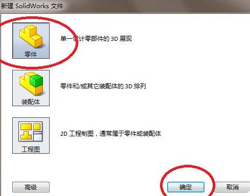
1. As shown in the picture, look at the red box selection, open Solidworks, and create a new part file.
2. As shown in the figure, the above reference plane is used as the sketch plane to create a sketch.
The specific operation is as follows: click [Sketch], and then click [Look Up Base Plane].
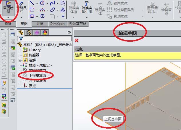
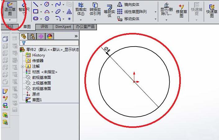
3. As shown in the figure, enter the sketch working state.
1) Click [Circle] in the toolbar
2) Set the origin of the coordinates as Draw a circle with the center
3) Mark the diameter? 6
4) Click [Exit Sketch].
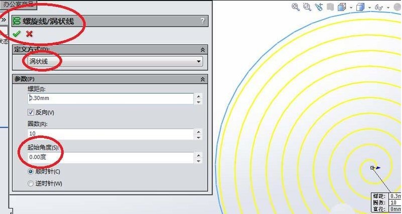
4. Create a swirl line.
As shown in the figure, find [Curve] in the feature toolbar, then find [Spiral/Vortex] in the drop-down menu of the curve, activate it, and the [Spiral/Vortex] will pop up as shown in the figure. Swirl Line] dialog box.
Pay attention to the red box selection. The default definition method is pitch and number of turns. We need to change it to a vortex line. Then, there is the starting angle. For convenience later, it is best to ensure that it is 0 degrees. Number of turns 10 and pitch 0.3. Click directly on the √ in the upper left corner to complete the creation of the vortex line.
5. As shown in the figure, continue to create the sketch. This time it is created using the right datum plane as the sketch plane, as follows:
1) Click [Sketch]
2) Click [Right datum plane].
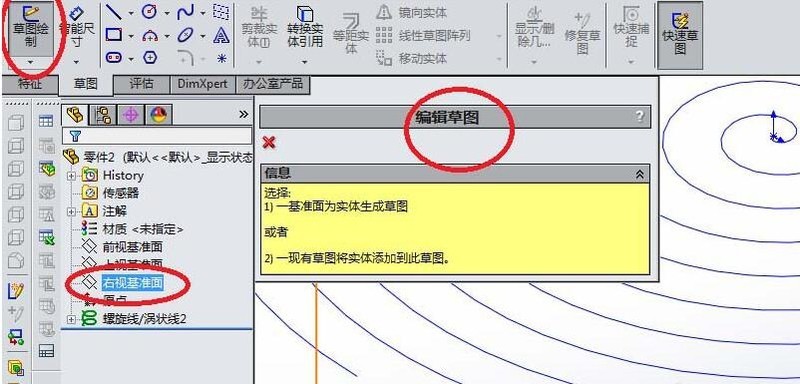
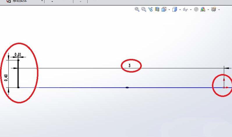
6. As shown in the picture, enter the slot sketch state, draw a rectangle, the size of the rectangle is 0.4x0.1, and position 0 according to the size as shown in the picture. In short, one requirement is that the starting point of one side of the rectangle must coincide with the starting point of the vortex line, otherwise, your subsequent scan will be unsuccessful.
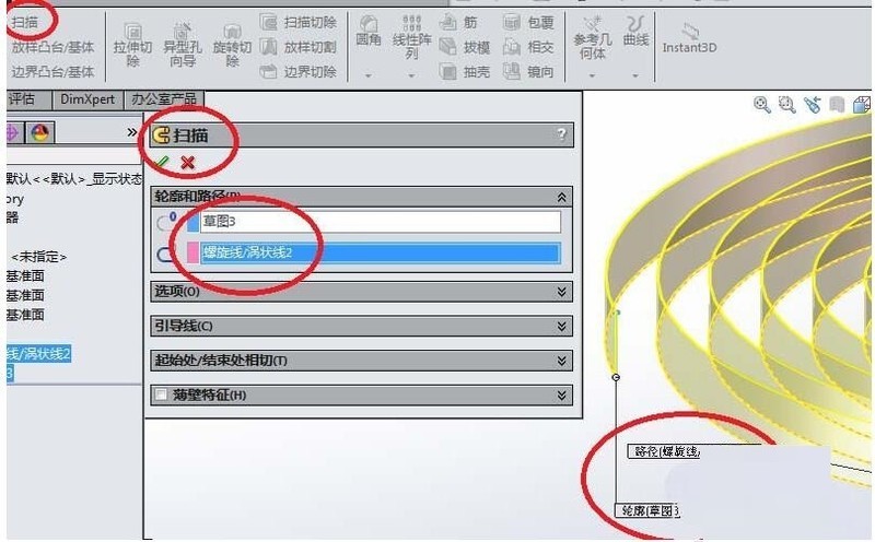
7. As shown in the picture, return to the feature toolbar, find [Scan], click it, and then the software will pop up the [Scan] dialog box, select the outline (rectangle) and path (vortex line), click √ in the upper left corner. Complete the creation of the coil spring.
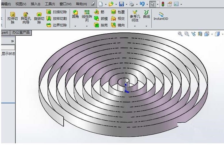
8. As shown in the picture, a coil spring is created.
The above is the detailed content of Detailed steps to create a coil spring model in Solidworks. For more information, please follow other related articles on the PHP Chinese website!

Hot AI Tools

Undresser.AI Undress
AI-powered app for creating realistic nude photos

AI Clothes Remover
Online AI tool for removing clothes from photos.

Undress AI Tool
Undress images for free

Clothoff.io
AI clothes remover

AI Hentai Generator
Generate AI Hentai for free.

Hot Article

Hot Tools

Notepad++7.3.1
Easy-to-use and free code editor

SublimeText3 Chinese version
Chinese version, very easy to use

Zend Studio 13.0.1
Powerful PHP integrated development environment

Dreamweaver CS6
Visual web development tools

SublimeText3 Mac version
God-level code editing software (SublimeText3)

Hot Topics
 how to unlink rockstar account from steam
Mar 11, 2025 pm 07:39 PM
This article explains how to unlink a Rockstar Games Social Club account from Steam. The process involves using the Rockstar Games Launcher to manage linked accounts, removing the Steam connection without impacting game progress or future Steam purc
 why is steam downloading so slow
Mar 11, 2025 pm 07:36 PM
Slow Steam downloads stem from various factors: network congestion (home or ISP), Steam/game server issues, limited bandwidth, high latency, and computer hardware limitations. Troubleshooting involves checking internet speed, optimizing Steam settin
![[PROVEN] Steam Error e87 Fix: Get Gaming Again in Minutes!](https://img.php.cn/upload/article/202503/18/2025031817560457401.jpg?x-oss-process=image/resize,m_fill,h_207,w_330) [PROVEN] Steam Error e87 Fix: Get Gaming Again in Minutes!
Mar 18, 2025 pm 05:56 PM
[PROVEN] Steam Error e87 Fix: Get Gaming Again in Minutes!
Mar 18, 2025 pm 05:56 PM
Article discusses causes of Steam Error e87, including network issues, security software, server problems, outdated clients, and corrupted files. Offers prevention and solution strategies.[159 characters]
 Steam Error e87: What It Is & How to Fix It
Mar 18, 2025 pm 05:51 PM
Steam Error e87 occurs during Steam client updates or launches due to connection issues. Fix it by restarting devices, checking server status, changing DNS, disabling security software, clearing cache, or reinstalling Steam.
 Steam Error e87: Why It Happens & 5 Ways to Fix It
Mar 18, 2025 pm 05:55 PM
Steam Error e87 disrupts gaming on Steam due to connectivity issues. The article discusses causes like unstable internet and server overload, and offers fixes like restarting Steam and checking for updates.
 How to Fix Steam Error Code e87: The ULTIMATE Guide
Mar 18, 2025 pm 05:51 PM
Article discusses fixing Steam Error Code e87, caused by network issues, corrupt files, or client problems. Provides troubleshooting steps and prevention tips.
 Easy Fix: Steam Error e87 Explained & Solved
Mar 18, 2025 pm 05:53 PM
Steam Error e87, caused by connectivity issues, can be fixed without reinstalling by restarting, checking internet, and clearing cache. Adjusting Steam settings helps prevent future occurrences.
 how to add page numbers in google docs
Mar 14, 2025 pm 02:57 PM
The article details how to add, customize, start from a specific page, and remove page numbers in Google Docs using step-by-step instructions.


