Python Matplotlib の基本: 一般的な使用法と例
Matplotlib
Matplotlib は、Python の MATLAB に似た描画ツールです。MATLAB に慣れている場合は、すぐに Matplotlib を使い始めることができます。
1. Matploblib を理解する
1.1 Figure
描画の前に、Figure オブジェクトが必要です。これは、描画を開始するための描画ボードが必要であると理解できます。
import matplotlib.pyplot as plt
fig = plt.figure()
1.2 軸
Figure オブジェクトを取得した後、描画する前に軸が必要です。軸がないと描画参照がないため、軸を追加する必要があります。実際に絵を描くのに使える紙とも言えます。
fig = plt.figure()
ax = fig.add_subplot(111)
ax.set(xlim=[0.5, 4.5], ylim=[-2, 8], title='An Example Axes',
       ylabel='Y-Axis', xlabel='X-Axis')
plt.show()のコードは、画像に軸を追加し、軸の X 軸と Y 軸の値の範囲を設定します (これらの設定は必須ではなく、後で説明します。これらの設定)の効果は以下のようになります。
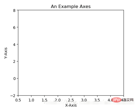
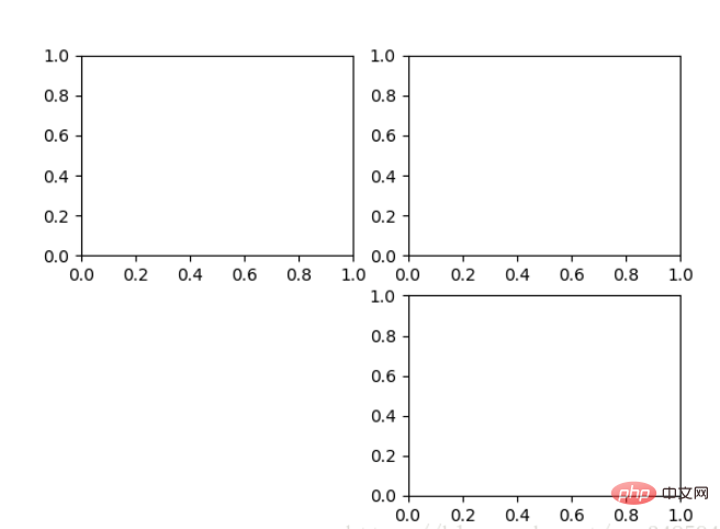
上記の fig.add_subplot(111) は Axes を追加するもので、パラメータの説明は次のとおりです。描画ボード ペイントの準備として、行 1、列 1 の最初の位置に Axes オブジェクトを生成します。軸は、fig.add_subplot(2, 2, 1) によって生成することもできます。最初の 2 つのパラメーターは、パネルの分割を決定します。たとえば、2, 2 は、パネル全体を 2 * 2 の正方形に分割します。 、3 番目のパラメーター値の範囲は [1, 2*2] で、どの軸を示すかを示します。次の例のように:
fig = plt.figure()
ax1 = fig.add_subplot(221)
ax2 = fig.add_subplot(222)
ax3 = fig.add_subplot(224)
1.3 複数の軸
上で追加した軸は少し弱いように見えるため、次の方法を使用します。すべての軸を一度に生成するために提供されています すべての軸:
fig, axes = plt.subplots(nrows=2, ncols=2)
axes[0,0].set(title='Upper Left')
axes[0,1].set(title='Upper Right')
axes[1,0].set(title='Lower Left')
axes[1,1].set(title='Lower Right')
fig は、今でも私たちがよく知っている製図板です。軸は 2 次元配列の形式で一般的にアクセスできるようになりました。これは、次の場合に特に便利です。ループ描画。
1.4 Axes Vs .pyplot
次のコードは見たことがある人も多いと思いますが、非常にシンプルでわかりやすいですが、以下の描画方法は単純な描画や簡単な描画にのみ適しています。 . .複雑な描画作業を扱う場合でも、描画を完了するために Axes を使用する必要があります。
plt.plot([1, 2, 3, 4], [10, 20, 25, 30], color='lightblue', linewidth=3)
plt.xlim(0.5, 4.5)
plt.show()
2. 基本的な描画 2D
2.1 Line
plot() 関数は、一連の点を描画し、それらを線で接続します。例を見てください:
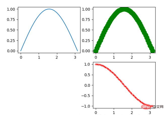
x = np.linspace(0, np.pi)
y_sin = np.sin(x)
y_cos = np.cos(x)

ax1.plot(x, y_sin)
ax2.plot(x, y_sin, 'go--', linewidth=2, markersize=12)
ax3.plot(x, y_cos, color='red', marker='+', linestyle='dashed')
上の 3 つの軸をペイントします。プロットでは、最初の 2 つのパラメーターは x 軸と y 軸のデータです。 ax2 の 3 番目のパラメーターは MATLAB スタイルの描画で、ax3 の色、マーカー、線のスタイルに対応します。
さらに、次の例のように、キーワード パラメーターによって描画することもできます。
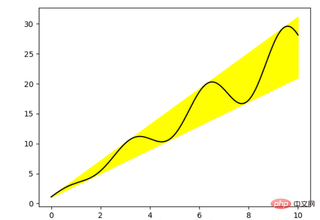
x = np.linspace(0, 10, 200)
data_obj = {'x': x,
            'y1': 2 * x + 1,
            'y2': 3 * x + 1.2,
            'mean': 0.5 * x * np.cos(2*x) + 2.5 * x + 1.1}

fig, ax = plt.subplots()

#填充两条线之间的颜色
ax.fill_between('x', 'y1', 'y2', color='yellow', data=data_obj)

# Plot the "centerline" with `plot`
ax.plot('x', 'mean', color='black', data=data_obj)

plt.show()上の図では、データのみが描画されていることがわかりました。部分が文字列で渡された場合、これらの文字列は data_obj のキーワードに対応し、この方法で描画すると、渡されたデータの中にキーワードに対応するデータが見つかり、描画されます。
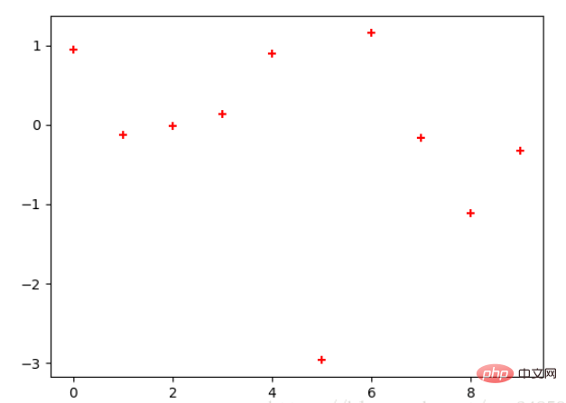
2.2 散布図
点を描画するだけで、線で接続しません。
x = np.arange(10)
y = np.random.randn(10)
plt.scatter(x, y, color='red', marker='+')
plt.show()
2.3 棒グラフ
棒グラフには 2 種類あり、1 つは横棒グラフ、もう 1 つは縦棒グラフです。以下の例を参照してください。
np.random.seed(1)
x = np.arange(5)
y = np.random.randn(5)

fig, axes = plt.subplots(ncols=2, figsize=plt.figaspect(1./2))

vert_bars = axes[0].bar(x, y, color='lightblue', align='center')
horiz_bars = axes[1].barh(x, y, color='lightblue', align='center')
#在水平或者垂直方向上画线
axes[0].axhline(0, color='gray', linewidth=2)
axes[1].axvline(0, color='gray', linewidth=2)
plt.show()
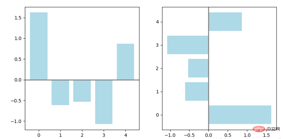
棒グラフは、各棒に対応するアーティスト配列も返します。たとえば、上の図のアーティスト配列のサイズは 5 です。これらのアーティストを使用して比較できます。次の例のように、グラフのスタイルを変更します:
fig, ax = plt.subplots()
vert_bars = ax.bar(x, y, color='lightblue', align='center')
# We could have also done this with two separate calls to `ax.bar` and numpy boolean indexing.
for bar, height in zip(vert_bars, y):
if height < 0:
bar.set(edgecolor='darkred', color='salmon', linewidth=3)
plt.show()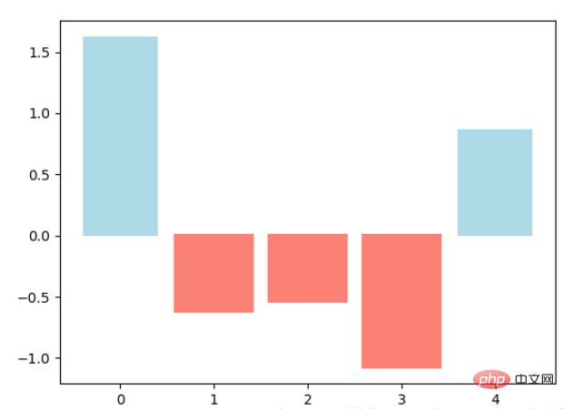
2.4 ヒストグラム
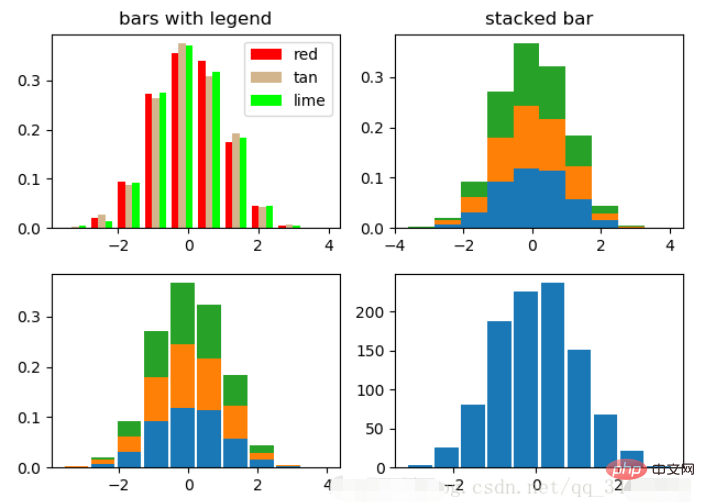
ヒストグラムは、数または頻度をカウントするために使用されます。
np.random.seed(19680801)

n_bins = 10
x = np.random.randn(1000, 3)

fig, axes = plt.subplots(nrows=2, ncols=2)
ax0, ax1, ax2, ax3 = axes.flatten()

colors = ['red', 'tan', 'lime']
ax0.hist(x, n_bins, density=True, histtype='bar', color=colors, label=colors)
ax0.legend(prop={'size': 10})
ax0.set_title('bars with legend')

ax1.hist(x, n_bins, density=True, histtype='barstacked')
ax1.set_title('stacked bar')

ax2.hist(x,  histtype='barstacked', rwidth=0.9)

ax3.hist(x[:, 0], rwidth=0.9)
ax3.set_title('different sample sizes')

fig.tight_layout()
plt.show() パラメータの density は、Y 軸が確率であるか数量であるかを制御します。最初の変数が返されました。 histtype ヒストグラムのスタイルを制御します。デフォルトは「bar」です。複数のバーの場合、それらはサブグラフ 1 のように隣接して表示されます。「barstacked」は、サブグラフ 1 のように積み重ねられることを意味します。 2、3 。 rwidth 幅を制御します。ギャップが残る場合があります。図 2 と 3 を比較してください。図 4 はデータが 1 つだけの場合です。
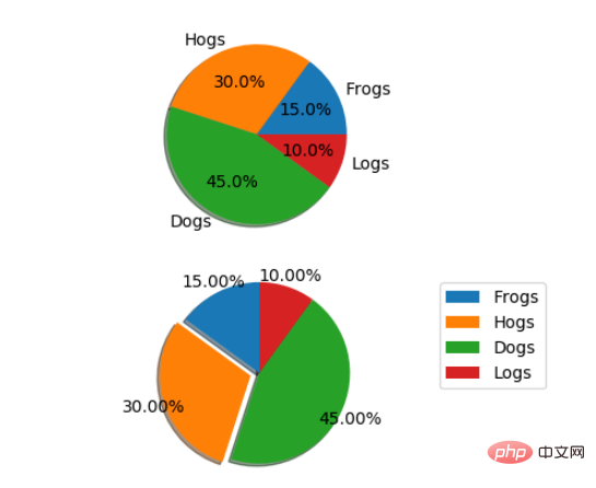
2.5 円グラフ
labels = 'Frogs', 'Hogs', 'Dogs', 'Logs'
sizes = [15, 30, 45, 10]
explode = (0, 0.1, 0, 0)  # only "explode" the 2nd slice (i.e. 'Hogs')

fig1, (ax1, ax2) = plt.subplots(2)
ax1.pie(sizes, labels=labels, autopct='%1.1f%%', shadow=True)
ax1.axis('equal')
ax2.pie(sizes, autopct='%1.2f%%', shadow=True, startangle=90, explode=explode,
    pctdistance=1.12)
ax2.axis('equal')
ax2.legend(labels=labels, loc='upper right')

plt.show()円グラフは、データの割合に基づいて自動的に円を描画します。 labels は、サブ図 1 に示すように、各ブロックのラベルです。 autopct=%1.1f%% は、フォーマットされたパーセント精度の出力、explode を意味し、特定のブロックを強調表示します。値が異なると強調表示効果も異なります。 pct distance=1.12パーセンテージと円の中心の間の距離。デフォルトは 0.6 です。
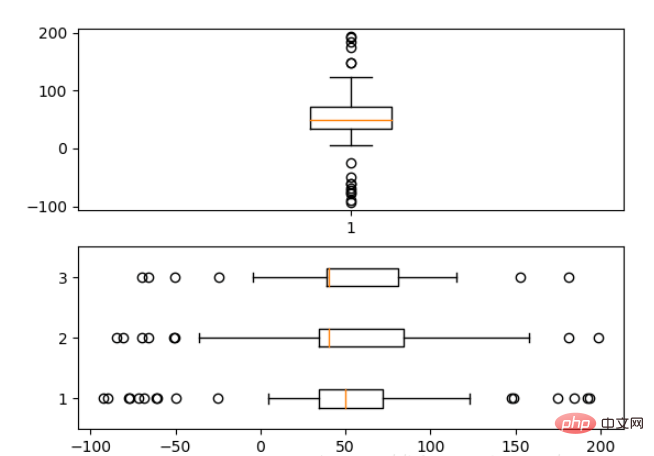
2.6 箱形图
为了专注于如何画图,省去数据的处理部分。 data 的 shape 为 (n, ), data2 的 shape 为 (n, 3)。
fig, (ax1, ax2) = plt.subplots(2)
ax1.boxplot(data)
ax2.boxplot(data2, vert=False) #控制方向
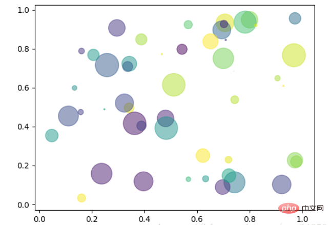
2.7 泡泡图
散点图的一种,加入了第三个值 s 可以理解成普通散点,画的是二维,泡泡图体现了Z的大小,如下例:
np.random.seed(19680801)


N = 50
x = np.random.rand(N)
y = np.random.rand(N)
colors = np.random.rand(N)
area = (30 * np.random.rand(N))**2  # 0 to 15 point radii

plt.scatter(x, y, s=area, c=colors, alpha=0.5)
plt.show()
2.8 等高线(轮廓图)
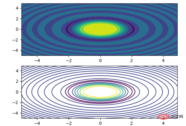
有时候需要描绘边界的时候,就会用到轮廓图,机器学习用的决策边界也常用轮廓图来绘画,见下例:
fig, (ax1, ax2) = plt.subplots(2)
x = np.arange(-5, 5, 0.1)
y = np.arange(-5, 5, 0.1)
xx, yy = np.meshgrid(x, y, sparse=True)
z = np.sin(xx**2 + yy**2) / (xx**2 + yy**2)
ax1.contourf(x, y, z)
ax2.contour(x, y, z)
上面画了两个一样的轮廓图,contourf会填充轮廓线之间的颜色。数据x, y, z通常是具有相同 shape 的二维矩阵。x, y 可以为一维向量,但是必需有 z.shape = (y.n, x.n) ,这里 y.n 和 x.n 分别表示x、y的长度。Z通常表示的是距离X-Y平面的距离,传入X、Y则是控制了绘制等高线的范围。
3 布局、图例说明、边界等
3.1区间上下限
当绘画完成后,会发现X、Y轴的区间是会自动调整的,并不是跟我们传入的X、Y轴数据中的最值相同。为了调整区间我们使用下面的方式:
ax.set_xlim([xmin, xmax])   #设置X轴的区间
ax.set_ylim([ymin, ymax])   #Y轴区间
ax.axis([xmin, xmax, ymin, ymax])   #X、Y轴区间
ax.set_ylim(bottom=-10)     #Y轴下限
ax.set_xlim(right=25)       #X轴上限
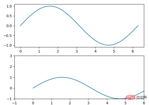
具体效果见下例:
x = np.linspace(0, 2*np.pi)
y = np.sin(x)
fig, (ax1, ax2) = plt.subplots(2)
ax1.plot(x, y)
ax2.plot(x, y)
ax2.set_xlim([-1, 6])
ax2.set_ylim([-1, 3])
plt.show()
可以看出修改了区间之后影响了图片显示的效果。
3.2 图例说明
我们如果我们在一个Axes上做多次绘画,那么可能出现分不清哪条线或点所代表的意思。这个时间添加图例说明,就可以解决这个问题了,见下例:
fig, ax = plt.subplots()
ax.plot([1, 2, 3, 4], [10, 20, 25, 30], label='Philadelphia')
ax.plot([1, 2, 3, 4], [30, 23, 13, 4], label='Boston')
ax.scatter([1, 2, 3, 4], [20, 10, 30, 15], label='Point')
ax.set(ylabel='Temperature (deg C)', xlabel='Time', title='A tale of two cities')
ax.legend()
plt.show()
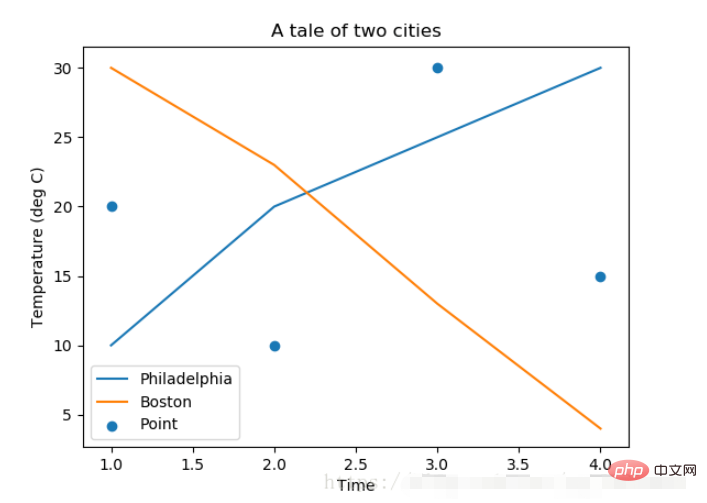
在绘图时传入 label 参数,并最后调用ax.legend()显示体力说明,对于 legend 还是传入参数,控制图例说明显示的位置:
| Location String | Location Code |
|---|---|
| ‘best’ | 0 |
| ‘upper right’ | 1 |
| ‘upper left’ | 2 |
| ‘lower left’ | 3 |
| ‘lower right’ | 4 |
| ‘right’ | 5 |
| ‘center left’ | 6 |
| ‘center right’ | 7 |
| ‘lower center’ | 8 |
| ‘upper center’ | 9 |
| ‘center’ | 10 |
3.3 区间分段
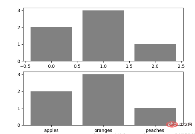
默认情况下,绘图结束之后,Axes 会自动的控制区间的分段。见下例:
data = [('apples', 2), ('oranges', 3), ('peaches', 1)]
fruit, value = zip(*data)

fig, (ax1, ax2) = plt.subplots(2)
x = np.arange(len(fruit))
ax1.bar(x, value, align='center', color='gray')
ax2.bar(x, value, align='center', color='gray')

ax2.set(xticks=x, xticklabels=fruit)

#ax.tick_params(axis='y', direction='inout', length=10) #修改 ticks 的方向以及长度
plt.show()
上面不仅修改了X轴的区间段,并且修改了显示的信息为文本。
3.4 布局
当我们绘画多个子图时,就会有一些美观的问题存在,例如子图之间的间隔,子图与画板的外边间距以及子图的内边距,下面说明这个问题:
fig, axes = plt.subplots(2, 2, figsize=(9, 9))
fig.subplots_adjust(wspace=0.5, hspace=0.3,
                    left=0.125, right=0.9,
                    top=0.9,    bottom=0.1)

#fig.tight_layout() #自动调整布局,使标题之间不重叠
plt.show()通过fig.subplots_adjust()我们修改了子图水平之间的间隔wspace=0.5,垂直方向上的间距hspace=0.3,左边距left=0.125 等等,这里数值都是百分比的。以 [0, 1] 为区间,选择left、right、bottom、top 注意 top 和 right 是 0.9 表示上、右边距为百分之10。不确定如果调整的时候,fig.tight_layout()是一个很好的选择。之前说到了内边距,内边距是子图的,也就是 Axes 对象,所以这样使用 ax.margins(x=0.1, y=0.1),当值传入一个值时,表示同时修改水平和垂直方向的内边距。
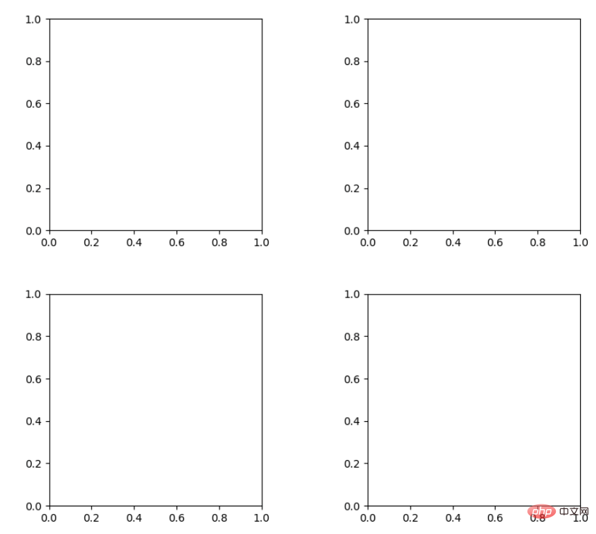
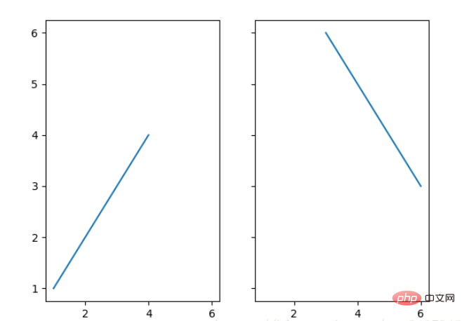
观察上面的四个子图,可以发现他们的X、Y的区间是一致的,而且这样显示并不美观,所以可以调整使他们使用一样的X、Y轴:
fig, (ax1, ax2) = plt.subplots(1, 2, sharex=True, sharey=True)
ax1.plot([1, 2, 3, 4], [1, 2, 3, 4])
ax2.plot([3, 4, 5, 6], [6, 5, 4, 3])
plt.show()
3.5 轴相关
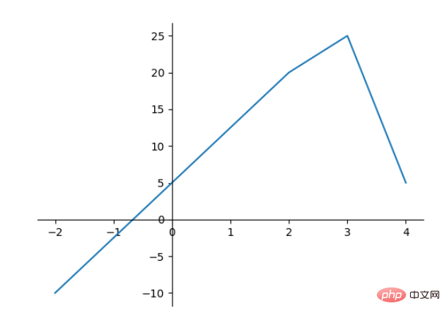
改变边界的位置,去掉四周的边框:
fig, ax = plt.subplots()
ax.plot([-2, 2, 3, 4], [-10, 20, 25, 5])
ax.spines['top'].set_visible(False)     #顶边界不可见
ax.xaxis.set_ticks_position('bottom')  # ticks 的位置为下方,分上下的。
ax.spines['right'].set_visible(False)   #右边界不可见
ax.yaxis.set_ticks_position('left')

# "outward"
# 移动左、下边界离 Axes 10 个距离
#ax.spines['bottom'].set_position(('outward', 10))
#ax.spines['left'].set_position(('outward', 10))

# "data"
# 移动左、下边界到 (0, 0) 处相交
ax.spines['bottom'].set_position(('data', 0))
ax.spines['left'].set_position(('data', 0))

# "axes"
# 移动边界,按 Axes 的百分比位置
#ax.spines['bottom'].set_position(('axes', 0.75))
#ax.spines['left'].set_position(('axes', 0.3))

plt.show()
以上がPython Matplotlib の基本: 一般的な使用法と例の詳細内容です。詳細については、PHP 中国語 Web サイトの他の関連記事を参照してください。

ホットAIツール

Undresser.AI Undress
リアルなヌード写真を作成する AI 搭載アプリ

AI Clothes Remover
写真から衣服を削除するオンライン AI ツール。

Undress AI Tool
脱衣画像を無料で

Clothoff.io
AI衣類リムーバー

AI Hentai Generator
AIヘンタイを無料で生成します。

人気の記事

ホットツール

メモ帳++7.3.1
使いやすく無料のコードエディター

SublimeText3 中国語版
中国語版、とても使いやすい

ゼンドスタジオ 13.0.1
強力な PHP 統合開発環境

ドリームウィーバー CS6
ビジュアル Web 開発ツール

SublimeText3 Mac版
神レベルのコード編集ソフト(SublimeText3)

ホットトピック
 7485
7485
 15
15
 1377
1377
 52
52
 77
77
 11
11
 19
19
 38
38
 mysqlは支払う必要がありますか
Apr 08, 2025 pm 05:36 PM
MySQLには、無料のコミュニティバージョンと有料エンタープライズバージョンがあります。コミュニティバージョンは無料で使用および変更できますが、サポートは制限されており、安定性要件が低く、技術的な能力が強いアプリケーションに適しています。 Enterprise Editionは、安定した信頼性の高い高性能データベースを必要とするアプリケーションに対する包括的な商業サポートを提供し、サポートの支払いを喜んでいます。バージョンを選択する際に考慮される要因には、アプリケーションの重要性、予算編成、技術スキルが含まれます。完璧なオプションはなく、最も適切なオプションのみであり、特定の状況に応じて慎重に選択する必要があります。
 インストール後にMySQLの使用方法
Apr 08, 2025 am 11:48 AM
この記事では、MySQLデータベースの操作を紹介します。まず、MySQLWorkBenchやコマンドラインクライアントなど、MySQLクライアントをインストールする必要があります。 1. mysql-uroot-pコマンドを使用してサーバーに接続し、ルートアカウントパスワードでログインします。 2。CreatedAtaBaseを使用してデータベースを作成し、データベースを選択します。 3. createTableを使用してテーブルを作成し、フィールドとデータ型を定義します。 4. INSERTINTOを使用してデータを挿入し、データをクエリし、更新することでデータを更新し、削除してデータを削除します。これらの手順を習得することによってのみ、一般的な問題に対処することを学び、データベースのパフォーマンスを最適化することでMySQLを効率的に使用できます。
 高負荷アプリケーションのMySQLパフォーマンスを最適化する方法は?
Apr 08, 2025 pm 06:03 PM
MySQLデータベースパフォーマンス最適化ガイドリソース集約型アプリケーションでは、MySQLデータベースが重要な役割を果たし、大規模なトランザクションの管理を担当しています。ただし、アプリケーションのスケールが拡大すると、データベースパフォーマンスのボトルネックが制約になることがよくあります。この記事では、一連の効果的なMySQLパフォーマンス最適化戦略を検討して、アプリケーションが高負荷の下で効率的で応答性の高いままであることを保証します。実際のケースを組み合わせて、インデックス作成、クエリ最適化、データベース設計、キャッシュなどの詳細な主要なテクノロジーを説明します。 1.データベースアーキテクチャの設計と最適化されたデータベースアーキテクチャは、MySQLパフォーマンスの最適化の基礎です。いくつかのコア原則は次のとおりです。適切なデータ型を選択し、ニーズを満たす最小のデータ型を選択すると、ストレージスペースを節約するだけでなく、データ処理速度を向上させることもできます。
 MySQLインストール後にデータベースのパフォーマンスを最適化する方法
Apr 08, 2025 am 11:36 AM
MySQLパフォーマンスの最適化は、インストール構成、インデックス作成、クエリの最適化、監視、チューニングの3つの側面から開始する必要があります。 1。インストール後、INNODB_BUFFER_POOL_SIZEパラメーターやclose query_cache_sizeなど、サーバーの構成に従ってmy.cnfファイルを調整する必要があります。 2。過度のインデックスを回避するための適切なインデックスを作成し、説明コマンドを使用して実行計画を分析するなど、クエリステートメントを最適化します。 3. MySQL独自の監視ツール(ShowProcessList、ShowStatus)を使用して、データベースの健康を監視し、定期的にデータベースをバックアップして整理します。これらの手順を継続的に最適化することによってのみ、MySQLデータベースのパフォーマンスを改善できます。
 mysqlはインターネットが必要ですか?
Apr 08, 2025 pm 02:18 PM
MySQLは、基本的なデータストレージと管理のためにネットワーク接続なしで実行できます。ただし、他のシステムとのやり取り、リモートアクセス、または複製やクラスタリングなどの高度な機能を使用するには、ネットワーク接続が必要です。さらに、セキュリティ対策(ファイアウォールなど)、パフォーマンスの最適化(適切なネットワーク接続を選択)、およびデータバックアップは、インターネットに接続するために重要です。
 MongoDBデータベースパスワードを表示するNAVICATの方法
Apr 08, 2025 pm 09:39 PM
Hash値として保存されているため、Navicatを介してMongoDBパスワードを直接表示することは不可能です。紛失したパスワードを取得する方法:1。パスワードのリセット。 2。構成ファイルを確認します(ハッシュ値が含まれる場合があります)。 3.コードを確認します(パスワードをハードコードできます)。
 hadidb:pythonの軽量で水平方向にスケーラブルなデータベース
Apr 08, 2025 pm 06:12 PM
hadidb:軽量で高レベルのスケーラブルなPythonデータベースHadIDB(HadIDB)は、Pythonで記述された軽量データベースで、スケーラビリティが高くなっています。 PIPインストールを使用してHADIDBをインストールする:PIPINSTALLHADIDBユーザー管理CREATEユーザー:CREATEUSER()メソッド新しいユーザーを作成します。 Authentication()メソッドは、ユーザーのIDを認証します。 fromhadidb.operationimportuseruser_obj = user( "admin"、 "admin")user_obj。
 MySQLワークベンチはMariadBに接続できますか
Apr 08, 2025 pm 02:33 PM
MySQLワークベンチは、構成が正しい場合、MariadBに接続できます。最初にコネクタタイプとして「mariadb」を選択します。接続構成では、ホスト、ポート、ユーザー、パスワード、およびデータベースを正しく設定します。接続をテストするときは、ユーザー名とパスワードが正しいかどうか、ポート番号が正しいかどうか、ファイアウォールが接続を許可するかどうか、データベースが存在するかどうか、MariadBサービスが開始されていることを確認してください。高度な使用法では、接続プーリングテクノロジーを使用してパフォーマンスを最適化します。一般的なエラーには、不十分な権限、ネットワーク接続の問題などが含まれます。エラーをデバッグするときは、エラー情報を慎重に分析し、デバッグツールを使用します。ネットワーク構成を最適化すると、パフォーマンスが向上する可能性があります


