vue3.x를 사용하여 순서도를 그리는 방법을 단계별로 안내해 드립니다.
vue3.x를 사용하여 흐름도를 그리는 방법은 무엇입니까? 다음 글에서는 vue3.x 기반의 순서도 그리기 방법을 알려드리겠습니다. 도움이 되셨으면 좋겠습니다!

GitHub-workflow
https://github.com/554246839/comComponent-test/tree/dev/src/comComponents/workflow
이것은 주로 워크플로 시나리오용입니다. 구현. (학습 영상 공유: vuejs 영상 튜토리얼)
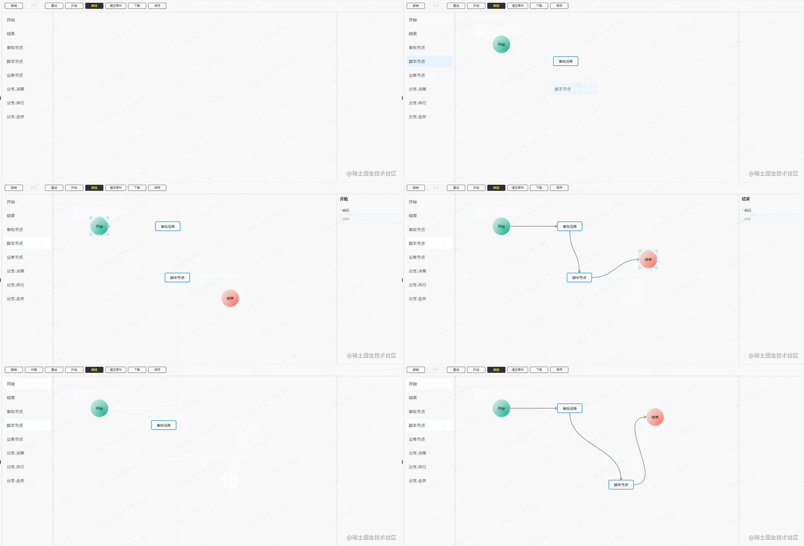
다음은 렌더링입니다:
전체 구조 레이아웃:

구현할 기능 목록:
- 구성 가능한 노드 및 연결선
- 노드 드래그 및 렌더링 및 연결선 그리기
- 노드 선택 및 연결선
- 노드 스타일 조정
- 노드 이동 시 흡착
- 실행 취소 및 복원
노드 및 연결선 구성 가능
- 노드 구성 정보
[
  {
    'id': '', // 每次渲染会生成一个新的id
    'name': 'start', // 节点名称,也就是类型
    'label': '开始', // 左侧列表节点的名称
    'displayName': '开始', // 渲染节点的显示名称(可修改)
    'className': 'icon-circle start', // 节点在渲染时候的class,可用于自定义节点的样式
    'attr': { // 节点的属性
      'x': 0, // 节点相对于画布的 x 位置
      'y': 0, // 节点相对于画布的 y 位置
      'w': 70, // 节点的初始宽度
      'h': 70  // 节点的初始高度
    },
    'next': [], // 节点出度的线
    'props': [] // 节点可配置的业务属性
  },
  // ...
]- 연결선 구성 정보
// next
[
  {
    // 连接线的id
    'id': 'ee1c5fa3-f822-40f1-98a1-f76db6a2362b',
    // 连接线的结束节点id
    'targetComponentId': 'fa7fbbfa-fc43-4ac8-8911-451d0098d0cb',
    // 连接线在起始节点的方向
    'directionStart': 'right',
    // 连接线在结束节点的方向
    'directionEnd': 'left',
    // 线的类型(直线、折线、曲线)
    'lineType': 'straight',
    // 显示在连接线中点的标识信息
    'extra': '',
    // 连接线在起始节点的id
    'componentId': 'fde2a040-3795-4443-a57b-af412d06c023'
  },
  // ...
]- 노드 속성 구성 구조
// props
[
  {
    // 表单的字段
    name: 'displayName',
    // 表单的标签
    label: '显示名称',
    // 字段的值
    value: '旅客运输',
    // 编辑的类型
    type: 'input',
    // 属性的必填字段
    required: true,
    // 表单组件的其它属性
    props: {
        placeholder: 'xxx'
    }
  },
  // ...
]드롭다운 선택 데이터의 경우 드롭다운 데이터가 많을 경우 구성에 저장된 데이터의 양 또한 매우 크므로 모든 드롭다운 데이터를 균일하게 관리할 수 있습니다. 왼쪽 구성 노드의 정보를 얻으면 모든 드롭다운 데이터가 추출되어 props의 이름 값으로 저장됩니다. 키를 사용할 때 props.name을 사용하세요. 해당 드롭다운 데이터를 가져옵니다.
또한 연결선의 속성을 구성해야 합니다. 노드의 속성과 비교할 때 각 노드의 속성은 다를 수 있지만 노드가 없으면 연결선이 존재하지 않으므로 먼저해야합니다. 연결선 속성을 준비하고, 연결선이 생성되면 연결선 속성에 추가합니다. 물론, 연결선의 속성을 동일하게 설정할 수도 있고, 노드에 따라 서로 다른 연결선의 속성을 설정할 수도 있습니다.
마지막으로 사용한 방법:
<template>
<workflow
ref="workflowRef"
@component-change="getActiveComponent"
@line-change="getActiveLine"
main-height="calc(100vh - 160px)">
</workflow>
</template>
<script setup>
import { ref } from 'vue'
import Workflow from '@/components/workflow'
import { commonRequest } from '@/utils/common'
import { ElMessage, ElMessageBox } from 'element-plus'
import { useRoute } from 'vue-router'
const route = useRoute()
const processId = route.query.processId // || 'testca08c433c34046e4bb2a8d3ce3ebc'
const processType = route.query.processType
// 切换的当前节点
const getActiveComponent = (component: Record<string, any>) => {
console.log('active component', component)
}
// 切换的当前连接线
const getActiveLine = (line: Record<string, any>) => {
console.log('active line', line)
}
const workflowRef = ref<InstanceType<typeof Workflow>>()
// 获取配置的节点列表
const getConfig = () => {
commonRequest(`/workflow/getWorkflowConfig?processType=${processType}`).then((res: Record<string, any>) => {
// 需要把所有的属性根据name转换成 key - value 形式
const props: Record<string, any> = {}
transferOptions(res.result.nodes, props)
// 设置左侧配置的节点数据
workflowRef.value?.setConfig(res.result)
getData(props)
})
}
// 获取之前已经配置好的数据
const getData = (props: Record<string, any>) => {
commonRequest(`/workflow/getWfProcess/${processId}`).then((res: Record<string, any>) => {
// 调整属性,这里是为了当配置列表的节点或者属性有更新,从而更新已配置的节点的属性
adjustProps(props, res.result.processJson)
// 设置已配置好的数据,并渲染
workflowRef.value?.setData(res.result.processJson, res.result.type || 'add')
})
}
const init = () => {
if (!processId) {
ElMessageBox.alert('当前没有流程id')
return
}
getConfig()
}
init()
const transferOptions = (nodes: Record<string, any>[], props: Record<string, any>) => {
nodes?.forEach((node: Record<string, any>) => {
props[node.name] = node.props
})
}
const adjustProps = (props: Record<string, any>, nodes: Record<string, any>[]) => {
nodes.forEach((node: Record<string, any>) => {
const oldProp: Record<string, any>[] = node.props
const res = transferKV(oldProp)
node.props = JSON.parse(JSON.stringify(props[node.name]))
node.props.forEach((prop: Record<string, any>) => {
prop.value = res[prop.name]
})
})
}
const transferKV = (props: Record<string, any>[]) => {
const res: Record<string, any> = {}
props.forEach((prop: Record<string, any>) => {
res[prop.name] = prop.value
})
return res
}
</script>노드를 드래그 앤 렌더링하고 연결선을 그립니다
노드 드래그에 대해서는 별로 말할 것도 없고 드래그와 관련된 사용법입니다. 주로 노드와 연결에 관한 것입니다. 렌더링 영역 라인 디자인.
여기서 렌더링 영역의 개념은 캔버스 요소를 캔버스 배경으로 사용하고 노드는 div 형식으로 렌더링되며 드래그된 위치는 캔버스의 상대 위치에 따라 이동됩니다. 대략적인 구조는 다음과 같습니다.
<template>
    <!-- 渲染区域的祖先元素 -->
    <div>
        <!-- canvas 画布,绝对于父级元素定位, inset: 0; -->
        <canvas></canvas>
        <!-- 节点列表渲染的父级元素,绝对于父级元素定位, inset: 0; -->
        <div>
            <!-- 节点1,绝对于父级元素定位 -->
            <div></div>
            <!-- 节点2,绝对于父级元素定位 -->
            <div></div>
            <!-- 节点3,绝对于父级元素定位 -->
            <div></div>
            <!-- 节点4,绝对于父级元素定位 -->
            <div></div>
        </div>
    </div>
</template>연결선 그리기는 다음 필드의 정보를 기반으로 targetComponentId 구성 요소의 위치를 찾은 다음 캔버스의 두 점 사이에 선을 그리는 것입니다.
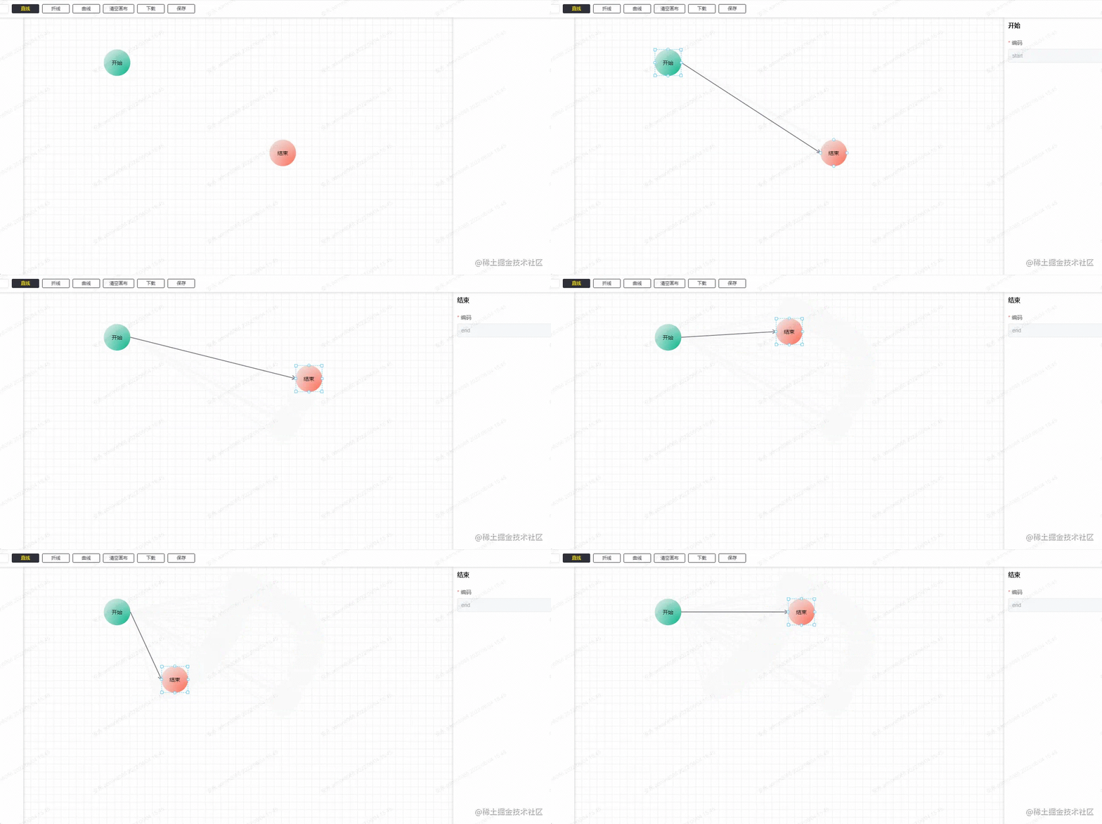
링크에는 직선, 다중선, 곡선의 3가지 유형이 있습니다.
- 선
선은 그리기 가장 쉽습니다. 두 점을 연결하기만 하면 됩니다.
// 绘制直线
const drawStraightLine = (
  ctx: CanvasRenderingContext2D,
  points: [number, number][],
  highlight?: boolean
) => {
  ctx.beginPath()
  ctx.moveTo(points[0][0], points[0][1])
  ctx.lineTo(points[1][0], points[1][1])
  // 是否是当前选中的连接线,当前连接线高亮
  shadowLine(ctx, highlight)
  ctx.stroke()
  ctx.restore()
  ctx.closePath()
}
- Polyline
폴리라인의 방식은 더 복잡합니다. 폴리라인은 연결선과 노드가 최대한 겹치지 않도록 해야 하기 때문에 각 연결선의 시나리오와 너비를 결정해야 하기 때문입니다. 두 노드의 높이도 계산에 고려되어야 합니다.
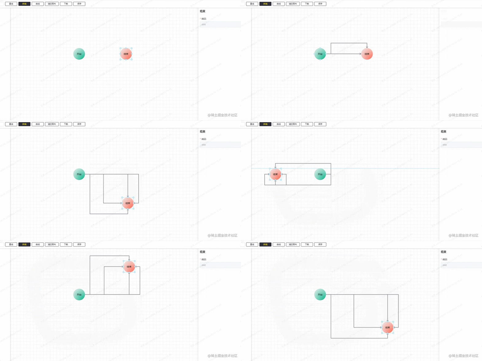
시작 노드에는 4개의 방향이 있고, 대상 노드에도 4개의 방향이 있으며, 대상 노드에는 시작 노드를 기준으로 4개의 사분면이 있으므로 엄밀히 말하면 총 4*4*4가 있습니다. = 64 종류의 장면. 이 장면의 폴리라인 포인트도 다릅니다. 최대는 4배이고 최소는 0배입니다. 이 64개의 좌표 포인트만 찾으려면 700줄의 코드가 필요합니다.
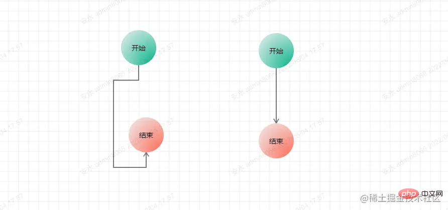
최종 그리기 방법은 직선과 동일합니다.
// 绘制折线
const drawBrokenLine = ({ ctx, points }: WF.DrawLineType, highlight?: boolean) => {
  ctx.beginPath()
  ctx.moveTo(points[0][0], points[0][1])
  for (let i = 1; i < points.length; i++) {
    ctx.lineTo(points[i][0], points[i][1])
  }
  shadowLine(ctx, highlight)
  ctx.stroke()
  ctx.restore()
  ctx.closePath()
}- Curve
폴리라인에 비해 곡선의 아이디어는 훨씬 간단하며, 그렇게 많은 시나리오를 고려할 필요가 없습니다. 폴리라인.
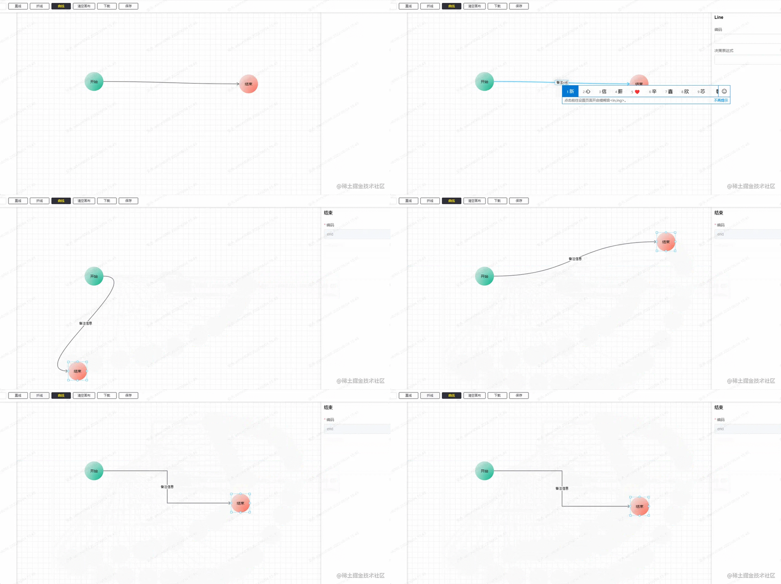
여기 폴리선은 3차 베지어 곡선으로 그려집니다. 4개의 고정점, 2개의 시작점과 끝점, 2개의 제어점만 찾으면 됩니다. 두 제어점의 좌표. 여기는 코드가 많지 않으니 직접 올려도 됩니다:
/**
 * Description: 计算三阶贝塞尔曲线的坐标
 */
import WF from '../type'

const coeff = 0.5
export default function calcBezierPoints({ startDire, startx, starty, destDire, destx, desty }: WF.CalcBezierType,
  points: [number, number][]) {

  const p = Math.max(Math.abs(destx - startx), Math.abs(desty - starty)) * coeff
  switch (startDire) {
    case 'down':
      points.push([startx, starty + p])
      break
    case 'up':
      points.push([startx, starty - p])
      break
    case 'left':
      points.push([startx - p, starty])
      break
    case 'right':
      points.push([startx + p, starty])
      break
    // no default
  }
  switch (destDire) {
    case 'down':
      points.push([destx, desty + p])
      break
    case 'up':
      points.push([destx, desty - p])
      break
    case 'left':
      points.push([destx - p, desty])
      break
    case 'right':
      points.push([destx + p, desty])
      break
    // no default
  }
}간단히 말하면 첫 번째 제어점은 시작점을 기준으로 계산되고, 두 번째 제어점은 끝점을 기준으로 계산됩니다. 계산 방법은 계속해서 노드를 기준으로 현재 지점의 방향을 기준으로 거리를 계산하는 것이며, 이 거리는 시작점과 끝점 사이의 최대 상대 거리의 절반을 기준으로 합니다(약간의 우회일 수 있습니다.) .).
그리기 방법:
// 绘制贝塞尔曲线
const drawBezier = ({ ctx, points }: WF.DrawLineType, highlight?: boolean) => {
  ctx.beginPath()
  ctx.moveTo(points[0][0], points[0][1])
  ctx.bezierCurveTo(
    points[1][0], points[1][1], points[2][0], points[2][1], points[3][0], points[3][1]
  )
  shadowLine(ctx, highlight)
  ctx.stroke()
  ctx.restore()
  ctx.globalCompositeOperation = 'source-over'    //目标图像上显示源图像
}节点与连接线的选择
节点是用 div 来渲染的,所以节点的选择可以忽略,然后就是连接点的选择,首先第一点是鼠标在移动的时候都要判断鼠标的当前位置下面是否有连接线,所以这里就有 3 种判断方法,呃... 严格来说是两种,因为折线是多条直线,所以是按直线的判断方法来。
// 判断当前鼠标位置是否有线
export const isAboveLine = (offsetX: number, offsetY: number, points: WF.LineInfo[]) => {
  for (let i = points.length - 1; i >= 0; --i) {
    const innerPonints = points[i].points
    let pre: [number, number], cur: [number, number]
    // 非曲线判断方法
    if (points[i].type !== 'bezier') {
      for (let j = 1; j < innerPonints.length; j++) {
        pre = innerPonints[j - 1]
        cur = innerPonints[j]
        if (getDistance([offsetX, offsetY], pre, cur) < 20) {
          return points[i]
        }
      }
    } else {
      // 先用 x 求出对应的 t,用 t 求相应位置的 y,再比较得出的 y 与 offsetY 之间的差值
      const tsx = getBezierT(innerPonints[0][0], innerPonints[1][0], innerPonints[2][0], innerPonints[3][0], offsetX)
      for (let x = 0; x < 3; x++) {
        if (tsx[x] <= 1 && tsx[x] >= 0) {
          const ny = getThreeBezierPoint(tsx[x], innerPonints[0], innerPonints[1], innerPonints[2], innerPonints[3])
          if (Math.abs(ny[1] - offsetY) < 8) {
            return points[i]
          }
        }
      }
      // 如果上述没有结果,则用 y 求出对应的 t,再用 t 求出对应的 x,与 offsetX 进行匹配
      const tsy = getBezierT(innerPonints[0][1], innerPonints[1][1], innerPonints[2][1], innerPonints[3][1], offsetY)
      for (let y = 0; y < 3; y++) {
        if (tsy[y] <= 1 && tsy[y] >= 0) {
          const nx = getThreeBezierPoint(tsy[y], innerPonints[0], innerPonints[1], innerPonints[2], innerPonints[3])
          if (Math.abs(nx[0] - offsetX) < 8) {
            return points[i]
          }
        }
      }
    }
  }

  return false
}直线的判断方法是点到线段的距离:
/**
 * 求点到线段的距离
 * @param {number} pt 直线外的点
 * @param {number} p 直线内的点1
 * @param {number} q 直线内的点2
 * @returns {number} 距离
 */
function getDistance(pt: [number, number], p: [number, number], q: [number, number]) {
  const pqx = q[0] - p[0]
  const pqy = q[1] - p[1]
  let dx = pt[0] - p[0]
  let dy = pt[1] - p[1]
  const d = pqx * pqx + pqy * pqy   // qp线段长度的平方
  let t = pqx * dx + pqy * dy     // p pt向量 点积 pq 向量(p相当于A点,q相当于B点,pt相当于P点)
  if (d > 0) {  // 除数不能为0; 如果为零 t应该也为零。下面计算结果仍然成立。
    t /= d      // 此时t 相当于 上述推导中的 r。
  }
  if (t < 0) {  // 当t(r)< 0时,最短距离即为 pt点 和 p点(A点和P点)之间的距离。
    t = 0
  } else if (t > 1) { // 当t(r)> 1时,最短距离即为 pt点 和 q点(B点和P点)之间的距离。
    t = 1
  }

  // t = 0,计算 pt点 和 p点的距离; t = 1, 计算 pt点 和 q点 的距离; 否则计算 pt点 和 投影点 的距离。
  dx = p[0] + t * pqx - pt[0]
  dy = p[1] + t * pqy - pt[1]

  return dx * dx + dy * dy
}关于曲线的判断方法比较复杂,这里就不多介绍, 想了解的可以去看这篇:如何判断一个坐标点是否在三阶贝塞尔曲线附近
连接线还有一个功能就是双击连接线后可以编辑这条连接线的备注信息。这个备注信息的位置是在当前连接线的中心点位置。所以我们需要求出中心点,这个相对简单。
// 获取一条直线的中点坐标
const getStraightLineCenterPoint = ([[x1, y1], [x2, y2]]: [number, number][]): [number, number] => {
  return [(x1 + x2) / 2, (y1 + y2) / 2]
}

// 获取一条折线的中点坐标
const getBrokenCenterPoint = (points: [number, number][]): [number, number] => {
  const lineDistancehalf = getLineDistance(points) >> 1

  let distanceSum = 0, pre = 0, tp: [number, number][] = [], distance = 0

  for (let i = 1; i < points.length; i++) {
    pre = getTwoPointDistance(points[i - 1], points[i])
    if (distanceSum + pre > lineDistancehalf) {
      tp = [points[i - 1], points[i]]
      distance = lineDistancehalf - distanceSum
      break
    }
    distanceSum += pre
  }

  if (!tp.length) {
    return [0, 0]
  }

  let x = tp[0][0], y = tp[0][1]

  if (tp[0][0] === tp[1][0]) {
    if (tp[0][1] > tp[1][1]) {
      y -= distance
    } else {
      y += distance
    }
  } else {
    if (tp[0][0] > tp[1][0]) {
      x -= distance
    } else {
      x += distance
    }
  }

  return [x, y]
}曲线的中心点位置,可以直接拿三阶贝塞尔曲线公式求出
// 获取三阶贝塞尔曲线的中点坐标
const getBezierCenterPoint = (points: [number, number][]) => {
  return getThreeBezierPoint(
    0.5, points[0], points[1], points[2], points[3]
  )
}

/**
 * @desc 获取三阶贝塞尔曲线的线上坐标
 * @param {number} t 当前百分比
 * @param {Array} p1 起点坐标
 * @param {Array} p2 终点坐标
 * @param {Array} cp1 控制点1
 * @param {Array} cp2 控制点2
 */
export const getThreeBezierPoint = (
  t: number,
  p1: [number, number],
  cp1: [number, number],
  cp2: [number, number],
  p2: [number, number]
): [number, number] => {
  const [x1, y1] = p1
  const [x2, y2] = p2
  const [cx1, cy1] = cp1
  const [cx2, cy2] = cp2
  const x =
    x1 * (1 - t) * (1 - t) * (1 - t) +
    3 * cx1 * t * (1 - t) * (1 - t) +
    3 * cx2 * t * t * (1 - t) +
    x2 * t * t * t
  const y =
    y1 * (1 - t) * (1 - t) * (1 - t) +
    3 * cy1 * t * (1 - t) * (1 - t) +
    3 * cy2 * t * t * (1 - t) +
    y2 * t * t * t
  return [x | 0, y | 0]
}在算出每一条的中心点位置后,在目标位置添加备注信息即可:

节点的样式调整
节点的样式调整主要是位置及大小,而这些属性就是节点里面的 attr,在相应的事件下根据鼠标移动的方向及位置,来调整节点的样式。
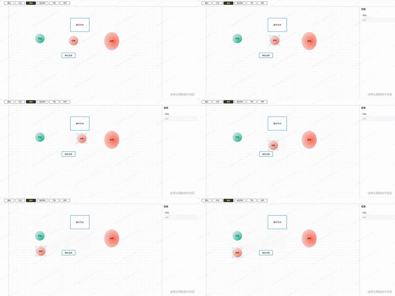
还有批量操作也是同样,不过批量操作是要先计算出哪些节点的范围。
// 获取范围选中内的组件
export const getSelectedComponent = (componentList: WF.ComponentType[], areaPosi: WF.Attr) => {
  let selectedArea: WF.Attr | null = null
  let minx = Infinity, miny = Infinity, maxx = -Infinity, maxy = -Infinity
  const selectedComponents = componentList.filter((component: WF.ComponentType) => {

    const res = areaPosi.x <= component.attr.x &&
      areaPosi.y <= component.attr.y &&
      areaPosi.x + areaPosi.w >= component.attr.x + component.attr.w &&
      areaPosi.y + areaPosi.h >= component.attr.y + component.attr.h

    if (res) {
      minx = Math.min(minx, component.attr.x)
      miny = Math.min(miny, component.attr.y)
      maxx = Math.max(maxx, component.attr.x + component.attr.w)
      maxy = Math.max(maxy, component.attr.y + component.attr.h)
    }
    return res
  })

  if (selectedComponents.length) {
    selectedArea = {
      x: minx,
      y: miny,
      w: maxx - minx,
      h: maxy - miny
    }
    return {
      selectedArea, selectedComponents
    }
  }
  return null
}
这个有个小功能没有做,就是在批量调整大小的时候,节点间的相对距离应该是不动的,这里忽略了。
节点移动时的吸附
这里的吸附功能其实是做了一个简单版的,就是 x 和 y 轴都只有一条校准线,且校准的优先级是从左至右,从上至下。

这里吸附的标准是节点的 6 个点:X 轴的左中右,Y 轴的上中下,当前节点在移动的时候,会用当前节点的 6 个点,一一去与其它节点的 6 个点做比较,在误差正负 2px 的情况,自动更新为0,即自定对齐。
因为移动当前节点时候,其它的节点是不动的,所以这里是做了一步预处理,即在鼠标按下去的时候,把其它的节点的 6 个点都线算出来,用 Set 结构保存,在移动的过程的比较中,计算量会相对较少。
// 计算其它节点的所有点位置
export const clearupPostions = (componentList: WF.ComponentType[], currId: string) => {
  // x 坐标集合
  const coordx = new Set<number>()
  // y 坐标集合
  const coordy = new Set<number>()

  componentList.forEach((component: WF.ComponentType) => {
    if (component.id === currId) {
      return
    }
    const { x, y, w, h } = component.attr
    coordx.add(x)
    coordx.add(x + (w >> 1))
    coordx.add(x + w)
    coordy.add(y)
    coordy.add(y + (h >> 1))
    coordy.add(y + h)
  })

  return [coordx, coordy]
}判读是否有可吸附的点
// 可吸附范围
const ADSORBRANGE = 2
// 查询是否有可吸附坐标
const hasAdsorbable = (
  coords: Set<number>[], x: number, y: number, w: number, h: number
) => {
  // x, y, w, h, w/2, h/2
  const coord: (number | null)[] = [null, null, null, null, null, null]
  // 查询 x 坐标
  for (let i = 0; i <= ADSORBRANGE; i++) {
    if (coords[0].has(x + i)) {
      coord[0] = i
      break
    }
    if (coords[0].has(x - i)) {
      coord[0] = -i
      break
    }
  }

  // 查询 y 坐标
  for (let i = 0; i <= ADSORBRANGE; i++) {
    if (coords[1].has(y + i)) {
      coord[1] = i
      break
    }
    if (coords[1].has(y - i)) {
      coord[1] = -i
      break
    }
  }

  // 查询 x + w 坐标
  for (let i = 0; i <= ADSORBRANGE; i++) {
    if (coords[0].has(x + w + i)) {
      coord[2] = i
      break
    }
    if (coords[0].has(x + w - i)) {
      coord[2] = -i
      break
    }
  }

  // 查询 y + h 坐标
  for (let i = 0; i <= ADSORBRANGE; i++) {
    if (coords[1].has(y + h + i)) {
      coord[3] = i
      break
    }
    if (coords[1].has(y + h - i)) {
      coord[3] = -i
      break
    }
  }

  // 查询 x + w/2 坐标
  for (let i = 0; i <= ADSORBRANGE; i++) {
    if (coords[0].has(x + (w >> 1) + i)) {
      coord[4] = i
      break
    }
    if (coords[0].has(x + (w >> 1) - i)) {
      coord[4] = -i
      break
    }
  }

  // 查询 y + h/2 坐标
  for (let i = 0; i <= ADSORBRANGE; i++) {
    if (coords[1].has(y + (h >> 1) + i)) {
      coord[5] = i
      break
    }
    if (coords[1].has(y + (h >> 1) - i)) {
      coord[5] = -i
      break
    }
  }

  return coord
}最后更新状态。
// 获取修正后的 x, y,还有吸附线的状态
export const getAdsordXY = (
  coords: Set<number>[], x: number, y: number, w: number, h: number
) => {
  const vals = hasAdsorbable(
    coords, x, y, w, h
  )

  let linex = null
  let liney = null

  if (vals[0] !== null) { // x
    x += vals[0]
    linex = x
  } else if (vals[2] !== null) { // x + w
    x += vals[2]
    linex = x + w
  } else if (vals[4] !== null) { // x + w/2
    x += vals[4]
    linex = x + (w >> 1)
  }

  if (vals[1] !== null) { // y
    y += vals[1]
    liney = y
  } else if (vals[3] !== null) { // y + h
    y += vals[3]
    liney = y + h
  } else if (vals[5] !== null) { // y + h/2
    y += vals[5]
    liney = y + (h >> 1)
  }

  return {
    x, y, linex, liney
  }
}撤销和恢复
撤销和恢复的功能是比较简单的,其实就是用栈来保存每一次需要保存的配置结构,就是要考虑哪些操作是可以撤销和恢复的,就是像节点移动,节点的新增和删除,连接线的连接,连接线的备注新增和编辑等等,在相关的操作下面入栈即可。
// 撤销和恢复操作
const cacheComponentList = ref<WF.ComponentType[][]>([])
const currentComponentIndex = ref(-1)
// 撤销
const undo = () => {
  componentRenderList.value = JSON.parse(JSON.stringify(cacheComponentList.value[--currentComponentIndex.value]))
  // 更新视图
  updateCanvas(true)
  cancelSelected()
}
// 恢复
const redo = () => {
  componentRenderList.value = JSON.parse(JSON.stringify(cacheComponentList.value[++currentComponentIndex.value]))
  // 更新视图
  updateCanvas(true)
  cancelSelected()
}
// 缓存入栈
const chacheStack = () => {
  if (cacheComponentList.value.length - 1 > currentComponentIndex.value) {
    cacheComponentList.value.length = currentComponentIndex.value + 1
  }
  cacheComponentList.value.push(JSON.parse(JSON.stringify(componentRenderList.value)))
  currentComponentIndex.value++
}
最后
这里主要的已经差不多都写了,其实最红还有一个挺有用的功能还没有做。就是改变已经绘制的连接线的起止点。
这里的思路是:先选中需要改变起止点的连接线,然后把鼠标移动到起止点的位置,将它从已经绘制的状态改为正在绘制的状态,然后再选择它的开始位置或者结束位置。这个后面看情况吧,有空就加上。
위 내용은 vue3.x를 사용하여 순서도를 그리는 방법을 단계별로 안내해 드립니다.의 상세 내용입니다. 자세한 내용은 PHP 중국어 웹사이트의 기타 관련 기사를 참조하세요!

핫 AI 도구

Undresser.AI Undress
사실적인 누드 사진을 만들기 위한 AI 기반 앱

AI Clothes Remover
사진에서 옷을 제거하는 온라인 AI 도구입니다.

Undress AI Tool
무료로 이미지를 벗다

Clothoff.io
AI 옷 제거제

Video Face Swap
완전히 무료인 AI 얼굴 교환 도구를 사용하여 모든 비디오의 얼굴을 쉽게 바꾸세요!

인기 기사

뜨거운 도구

메모장++7.3.1
사용하기 쉬운 무료 코드 편집기

SublimeText3 중국어 버전
중국어 버전, 사용하기 매우 쉽습니다.

스튜디오 13.0.1 보내기
강력한 PHP 통합 개발 환경

드림위버 CS6
시각적 웹 개발 도구

SublimeText3 Mac 버전
신 수준의 코드 편집 소프트웨어(SublimeText3)

뜨거운 주제
 7694
7694
 15
15
 1640
1640
 14
14
 1393
1393
 52
52
 1287
1287
 25
25
 1229
1229
 29
29
 vue.js vs. React : 프로젝트 별 고려 사항
Apr 09, 2025 am 12:01 AM
vue.js는 중소형 프로젝트 및 빠른 반복에 적합한 반면 React는 크고 복잡한 응용 프로그램에 적합합니다. 1) vue.js는 사용하기 쉽고 팀이 불충분하거나 프로젝트 규모가 작는 상황에 적합합니다. 2) React는 더 풍부한 생태계를 가지고 있으며 고성능 및 복잡한 기능적 요구가있는 프로젝트에 적합합니다.
 Vue에서 부트 스트랩을 사용하는 방법
Apr 07, 2025 pm 11:33 PM
vue.js에서 bootstrap 사용은 5 단계로 나뉩니다 : Bootstrap 설치. main.js.의 부트 스트랩 가져 오기 부트 스트랩 구성 요소를 템플릿에서 직접 사용하십시오. 선택 사항 : 사용자 정의 스타일. 선택 사항 : 플러그인을 사용하십시오.
 Vue 용 버튼에 기능을 추가하는 방법
Apr 08, 2025 am 08:51 AM
HTML 템플릿의 버튼을 메소드에 바인딩하여 VUE 버튼에 함수를 추가 할 수 있습니다. 메소드를 정의하고 VUE 인스턴스에서 기능 로직을 작성하십시오.
 Vue에서 시계를 사용하는 방법
Apr 07, 2025 pm 11:36 PM
vue.js의 시계 옵션을 사용하면 개발자가 특정 데이터의 변경 사항을들을 수 있습니다. 데이터가 변경되면 콜백 기능을 트리거하여 업데이트보기 또는 기타 작업을 수행합니다. 구성 옵션에는 즉시 콜백을 실행할지 여부와 DEEP를 지정하는 즉시 포함되며, 이는 객체 또는 어레이에 대한 변경 사항을 재귀 적으로 듣는 지 여부를 지정합니다.
 Vue 다중 페이지 개발은 무엇을 의미합니까?
Apr 07, 2025 pm 11:57 PM
VUE 멀티 페이지 개발은 vue.js 프레임 워크를 사용하여 응용 프로그램을 구축하는 방법입니다. 여기서 응용 프로그램은 별도의 페이지로 나뉩니다. 코드 유지 보수 : 응용 프로그램을 여러 페이지로 분할하면 코드를보다 쉽게 관리하고 유지 관리 할 수 있습니다. 모듈 식 : 각 페이지는 쉬운 재사용 및 교체를 위해 별도의 모듈로 사용할 수 있습니다. 간단한 라우팅 : 페이지 간의 탐색은 간단한 라우팅 구성을 통해 관리 할 수 있습니다. SEO 최적화 : 각 페이지에는 자체 URL이있어 SEO가 도움이됩니다.
 Vue Traversal 사용 방법
Apr 07, 2025 pm 11:48 PM
vue.js가 트래버스 어레이 및 객체에 대한 세 가지 일반적인 방법이 있습니다. V- 결합 지시문은 V-FOR와 함께 사용하여 각 요소의 속성 값을 동적으로 설정할 수 있습니다. .MAP 메소드는 배열 요소를 새 배열로 변환 할 수 있습니다.
 Vue의 div로 점프하는 방법
Apr 08, 2025 am 09:18 AM
VUE에서 DIV 요소를 점프하는 두 가지 방법이 있습니다. VUE 라우터를 사용하고 라우터 링크 구성 요소를 추가하십시오. @Click 이벤트 리스너를 추가하고 이것을 호출하십시오. $ router.push () 메소드를 점프하십시오.
 태그를 vue로 점프하는 방법
Apr 08, 2025 am 09:24 AM
VUE에서 태그의 점프를 구현하는 방법에는 다음이 포함됩니다. HTML 템플릿의 A 태그를 사용하여 HREF 속성을 지정합니다. VUE 라우팅의 라우터 링크 구성 요소를 사용하십시오. javaScript 에서이. $ router.push () 메소드를 사용하십시오. 매개 변수는 쿼리 매개 변수를 통해 전달 될 수 있으며 동적 점프를 위해 라우터 옵션에서 경로가 구성됩니다.


