
This article introduces the knowledge related to Mysql's InnoDB index, from various trees to index principles to storage details.
InnoDB is the default storage engine of Mysql (before Mysql5.5.5 it was MyISAM, document). For the purpose of efficient learning, this article mainly introduces InnoDB, with a small amount of MyISAM for comparison.
This article was summarized during my study process. The content mainly comes from books and blogs (references will be given). I added some of my own understanding in the process. Please point out any inaccuracies in the description.
Originally I didn’t plan to start with the binary search tree, because there are already too many related articles on the Internet, but considering that clear illustrations are very helpful for understanding the problem To help, and to ensure the completeness of the article, this part was finally added.
Let’s take a look at several tree structures first:
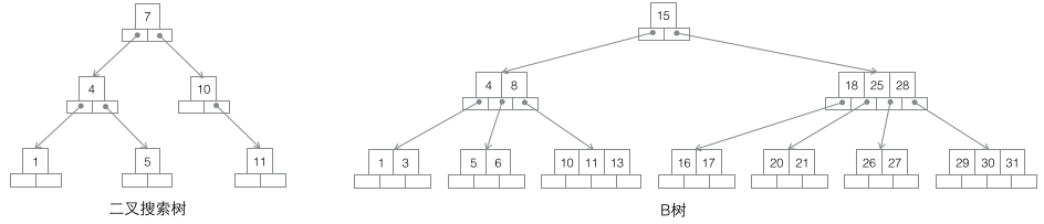
1 Search binary tree: Each node has two child nodes. The increase in the amount of data will inevitably lead to a rapid increase in height. Obviously this is not suitable as a Infrastructure for massive data storage.
2 B-tree: An m-order B-tree is a balanced m-way search tree. The most important property is that the number of keywords j contained in each non-root node satisfies: ┌m/2┐ - 1 <= j <= m - 1; the number of child nodes of a node will be greater than the number of keywords. 1 more, so that the keyword becomes the split mark of the child node. Generally, the keywords are drawn in the middle of the child nodes in the diagram, which is very vivid and easy to distinguish from the B+ tree behind. Since the data exists in both leaf nodes and non-leaf nodes, it is impossible to simply traverse the keywords in the B-tree in order, and the in-order traversal method must be used.
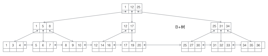
3 B+ tree: An m-order B-tree is a balanced m-way search tree. The most important property is that the number of keywords j contained in each non-root node satisfies: ┌m/2┐ - 1 <= j <= m; the number of subtrees can be as many as the keywords at most. Non-leaf nodes store the smallest keyword in the subtree. At the same time, data nodes only exist in leaf nodes, and horizontal pointers are added between leaf nodes, making it very easy to sequentially traverse all data.
4 B* tree: An m-order B-tree is a balanced m-way search tree. The two most important properties are 1. The number of keywords j contained in each non-root node satisfies: ┌m2/3┐ - 1 <= j <= m; 2. Horizontal pointers are added between non-leaf nodes.
The three trees B/B+/B* have similar operations, such as retrieval/ Insert/delete nodes. Here we only focus on the situation of inserting nodes, and only analyze their insertion operations when the current node is full, because this action is slightly complicated and can fully reflect the differences between several trees. In contrast, retrieving nodes is relatively easy to implement, while deleting nodes only requires completing the reverse process of insertion (in practical applications, deletion is not the complete reverse operation of insertion, and data is often only deleted and the space is reserved for subsequent use).
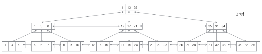
Let’s first look at the splitting of the B-tree. The red value in the figure below is the newly inserted node each time. Whenever a node is full, a split needs to occur (split is a recursive process, refer to the insertion in 7 below, which results in a two-level split). Since the non-leaf nodes of the B-tree also store key values, the full node after the split The values will be distributed in three places: 1. the original node, 2. the parent node of the original node, and 3. the new sibling node of the original node (refer to the insertion process in 5 and 7). Splitting may cause the height of the tree to increase (refer to the insertion process of 3 and 7), or it may not affect the height of the tree (refer to the insertion process of 5 and 6).
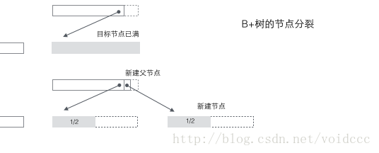
Split of B+ tree: When a node is full, allocate a new node and copy 1/2 of the data in the original node to the new node , and finally add the pointer of the new node to the parent node; the split of the B+ tree only affects the original node and the parent node, but not the sibling nodes, so it does not need a pointer to the sibling node.
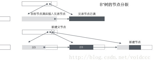
Split of B* tree: When a node is full, if its next sibling node is not full, then move part of the data to the sibling node, then insert keywords into the original node, and finally modify the parent node Click the keyword of the sibling node (because the keyword range of the sibling node has changed). If the brothers are also full, add a new node between the original node and the sibling node, copy 1/3 of the data to the new node, and finally add the pointer of the new node to the parent node. It can be seen that the splitting of the B* tree is very clever, because the B* tree must ensure that the split nodes are still 2/3 full. If the B+ tree method is used, simply dividing the full nodes into two will lead to Each node is only 1/2 full, which does not meet the requirements of the B* tree. Therefore, the strategy adopted by the B* tree is to continue inserting sibling nodes after the current node is full (this is why the B* tree needs to add a linked list between brothers at non-leaf nodes) until the sibling nodes are also filled, and then pull up the sibling nodes. Together, you and your brother nodes contribute 1/3 to establish a new node. The result is that the three nodes are exactly 2/3 full, meeting the requirements of the B* tree, and everyone is happy.
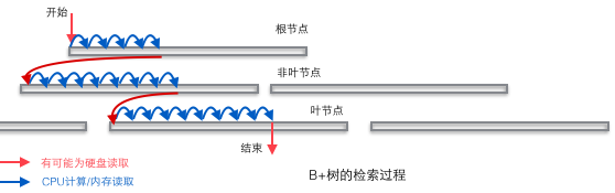
The B+ tree is suitable as the basic structure of the database entirely because of the two-layer storage structure of computer memory and mechanical hard disk. The memory can complete fast random access (random access means giving any address and asking to return the data stored at this address) but the capacity is small. The random access of the hard disk requires mechanical action (1 head movement, 2 disk rotation), and the access efficiency is several orders of magnitude lower than that of the memory, but the hard disk has a larger capacity. The typical database capacity greatly exceeds the available memory size, which determines that retrieving a piece of data in the B+ tree is likely to require several disk IO operations to complete. As shown in the figure below: Usually the action of reading down a node may be a disk IO operation, but non-leaf nodes are usually loaded into memory in the initial stage to speed up access. At the same time, in order to improve the speed of horizontal traversal between nodes, the blue CPU calculation/memory reading in the figure may be optimized into a binary search tree (the page directory mechanism in InnoDB) in a real database.
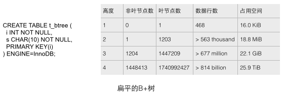
The B+ tree in a real database should be very flat. You can verify how flat the B+ tree in InnoDB is by sequentially inserting enough data into the table. We create a test table with only simple fields through the CREATE statement as shown below, and then continue to add data to fill this table. Several intuitive conclusions can be analyzed through the statistical data in the figure below (see reference 1 for the source). These conclusions macroscopically show the scale of the B+ tree in the database.
1 Each leaf node stores 468 rows of data, and each non-leaf node stores approximately 1200 key values. This is a balanced 1200-way search tree!
2 For a table with a capacity of 22.1G, it only needs a B+ tree with a height of 3 to store it. This capacity can probably meet the needs of many applications. If the height is increased to 4, the storage capacity of the B+ tree immediately increases to a huge 25.9T!
3 For a table with a capacity of 22.1G, the height of the B+ tree is 3. If you want to load all non-leaf nodes into the memory, you only need less than 18.8M of memory (how did you come to this conclusion? Because For a tree with a height of 2, 1203 leaf nodes only require 18.8M space, while the height of the 22.1G secondary table is 3 and there are 1204 non-leaf nodes. At the same time, we assume that the size of the leaf nodes is larger than the non-leaf nodes, because the leaves are larger. The node stores row data instead of leaf nodes (only keys and a small amount of data). It only uses such a small amount of memory to ensure that the required data can be retrieved in only one disk IO operation, which is very efficient.
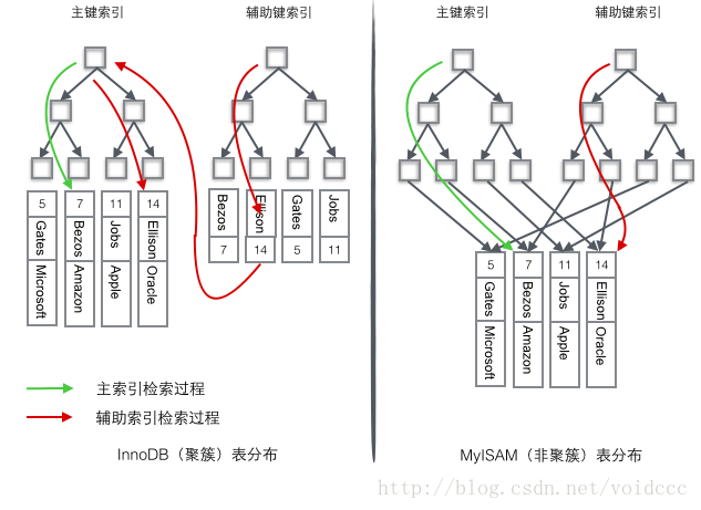
It can be said that the database must have an index. Without an index, the retrieval process becomes a sequential search, and the time complexity of O(n) is almost unbearable. It is very easy to imagine how a table consisting of only a single key can be indexed using a B+ tree, as long as the key is stored in the node of the tree. When a database record contains multiple fields, a B+ tree can only store the primary key. If a non-primary key field is retrieved, the primary key index loses its function and becomes a sequential search again. At this time, a second set of indexes should be established on the second column to be retrieved. This index is organized by independent B+ trees. There are two common methods to solve the problem of multiple B+ trees accessing the same set of table data, one is called clustered index (clustered index), and the other is called non-clustered index (secondary index). Although these two names are both called indexes, they are not a separate index type, but a data storage method. For clustered index storage, row data and primary key B+ trees are stored together. Secondary key B+ trees only store secondary keys and primary keys. Primary key and non-primary key B+ trees are almost two types of trees. For non-clustered index storage, the primary key B+ tree stores pointers to the actual data rows in the leaf nodes instead of the primary key.
InnoDB uses a clustered index to organize the primary key into a B+ tree, and the row data is stored on the leaf nodes. If you use the condition "where id = 14" to find the primary key, follow the The B+ tree retrieval algorithm can find the corresponding leaf node and then obtain the row data. If you perform a conditional search on the Name column, you need two steps: the first step is to retrieve the Name in the auxiliary index B+ tree, and reach its leaf node to obtain the corresponding primary key. The second step uses the primary key to perform another B+ tree retrieval operation on the primary index B+ tree species, and finally reaches the leaf node to obtain the entire row of data.
MyISM uses a non-clustered index. The two B+ trees of the non-clustered index look no different. The structure of the nodes is exactly the same but the stored content is different. The nodes of the primary key index B+ tree store the primary key. The secondary key index B+ tree stores secondary keys. The table data is stored in a separate place. The leaf nodes of the two B+ trees use an address to point to the real table data. For the table data, there is no difference between the two keys. Since the index tree is independent, retrieval by secondary key does not require access to the index tree for the primary key.
In order to more vividly illustrate the difference between these two indexes, we assume that a table stores 4 rows of data as shown below. Among them, Id serves as the primary index and Name serves as the secondary index. The diagram clearly shows the difference between clustered index and non-clustered index.

We focus on the clustered index. It seems that the efficiency of the clustered index is obviously lower than that of the non-clustered index, because every time Using the auxiliary index to search requires two B+ tree searches. Isn't this unnecessary? What are the advantages of clustered index?
1 Since the row data and leaf nodes are stored together, the primary key and row data are loaded into the memory together. When the leaf node is found, the row data can be returned immediately. If the data is organized according to the primary key Id, Get data faster.
2 The auxiliary index uses the primary key as a "pointer" instead of using the address value as the pointer. The advantage is that it reduces the maintenance work of the auxiliary index when row movement or data page splitting occurs, using the primary key value as a pointer. This will make the auxiliary index take up more space. The benefit is that InnoDB does not need to update the "pointer" in the auxiliary index when moving rows. That is to say, the position of the row (located through the 16K Page in the implementation, which will be covered later) will change as the data in the database is modified (the previous B+ tree node split and the Page split), and you can use a clustered index. It is guaranteed that no matter how the nodes of the primary key B+ tree change, the auxiliary index tree will not be affected.
If the previous content is biased towards explaining the principles, then the later part will start to involve the specific implementation.
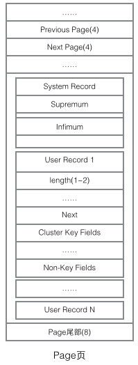
To understand the implementation of InnoDB, we must mention the Page structure. Page is the most basic component of the entire InnoDB storage and the smallest unit of InnoDB disk management. All content related to the database is stored in this Page structure. Pages are divided into several types. Common page types include data page (B-tree Node), Undo page (Undo Log Page), system page (System Page), transaction data page (Transaction System Page), etc. The size of a single Page is 16K (controlled by the compilation macro UNIV_PAGE_SIZE). Each Page is uniquely identified by a 32-bit int value, which corresponds to InnoDB's maximum storage capacity of 64TB (16Kib * 2^32 = 64Tib). The basic structure of a Page is as shown below:
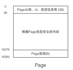
Every Page has a common head and tail, but the content in the middle changes according to the type of Page. There are some data that we care about in the header of the Page. The following figure shows the detailed information of the Page's header:
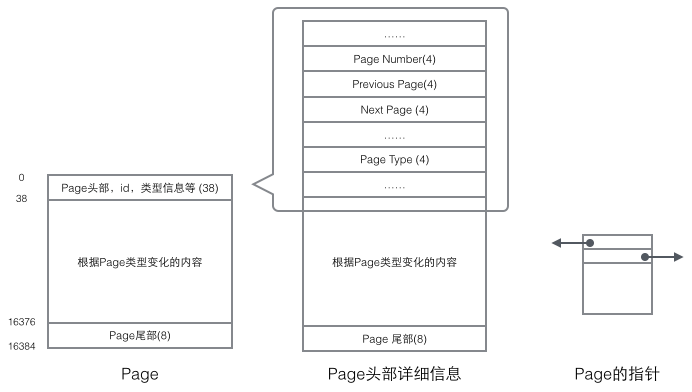
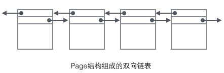
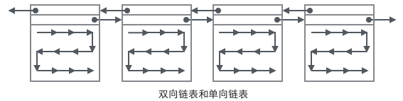
We focus on the data Fields related to the organizational structure: The header of the Page stores two pointers, pointing to the previous Page and the next Page respectively. The header also contains Page type information and a number used to uniquely identify the Page. Based on these two pointers, we can easily imagine that Page is linked into a doubly linked list structure.
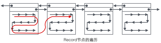
Looking at the main content of the Page, we mainly focus on the storage of row data and indexes. They are all located in the User Records section of the Page. User Records occupy most of the space of the Page. , User Records are composed of Records one by one, and each record represents a node (non-leaf node and leaf node) on the index tree. Within a Page, the head and tail of a singly linked list are represented by two records with fixed content. "Infimum" in the form of a string represents the beginning, and "Supremum" represents the end. These two Records used to represent the beginning and end are stored in the System Records segment. The System Records and User Records are two parallel segments. There are 4 different Records in InnoDB, which are 1 primary key index tree non-leaf node, 2 primary key index tree leaf node, 3 auxiliary key index tree non-leaf node, and 4 auxiliary key index tree leaf node. There are some differences in the Record format of these four nodes, but they all store Next pointers pointing to the next Record. We will introduce these four types of nodes in detail later. For now, you only need to treat Record as a singly linked list node that stores data and contains a Next pointer.
User Record exists in the form of a singly linked list in the Page. Initially, the data is arranged in the order of insertion, but as new data is inserted and old data is deleted, , the physical order of data will become chaotic, but they still maintain the logical order.
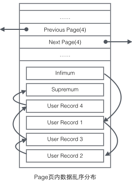
Combining the organizational form of User Record with several Pages, you can see a slightly complete form.
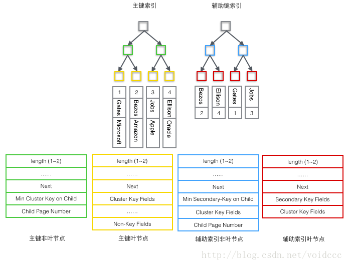
1 Primary index tree non-leaf node (green)
1 The smallest value in the primary key stored in the child node (Min Cluster Key on Child), this is the B+ tree Necessary, its function is to locate the specific record location in a Page. 2 The number of the Page where the smallest value is located (Child Page Number), used to locate the Record.2 Primary index tree leaf node (yellow)
1 Primary key (Cluster Key Fields), necessary for B+ tree, is also part of the data row 2 All columns except the primary key (Non-Key Fields), which is the set of all other columns of the data row except the primary key. The two parts 1 and 2 here add up to a complete data row.3 Auxiliary index tree non-leaf node non (blue)
1 The smallest value among the auxiliary key values stored in the child node (Min Secondary-Key on Child), which is necessary for B+ tree. Its function is to locate the specific record position in a Page. 2 Primary key value (Cluster Key Fields), why do non-leaf nodes store primary keys? Because the auxiliary index can be non-unique, but the B+ tree requires that the key value must be unique, so the value of the auxiliary key and the value of the primary key are combined here as the real key value in the B+ tree, ensuring uniqueness. But this also results in the non-leaf nodes in the auxiliary index B+ tree being 4 bytes more than the leaf nodes. (That is, the blue node in the picture below is 4 bytes more than the red node)3 The number of the Page where the smallest value is located (Child Page Number), used to locate the Record.
4 Auxiliary index tree leaf node (red)
1 Auxiliary index key value (Secondary Key Fields), which is necessary for B+ tree.
2 Primary key value (Cluster Key Fields), used to do another B+ tree search in the main index tree to find the entire record.
The following is the most important part of this article. Combining the structure of the B+ tree and the contents of the four types of Record introduced earlier, we can finally draw a panoramic picture. Since the B+ tree of the auxiliary index has a similar structure to the primary key index, only the structure diagram of the primary key index tree is drawn here, which only contains two types of nodes: "primary key non-leaf nodes" and "primary key leaf nodes", which are the ones in the figure above. green and yellow parts.
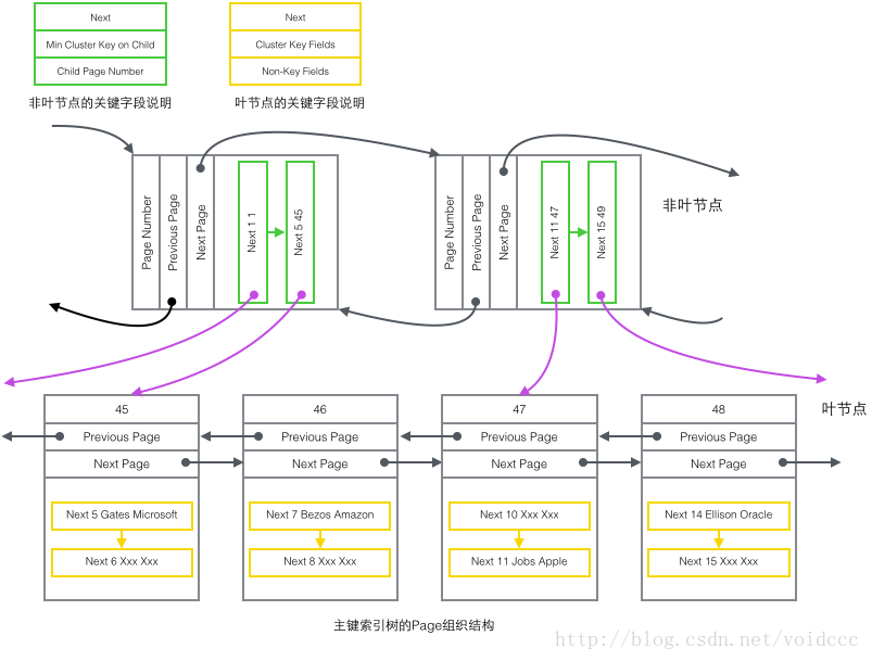
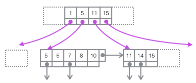
Restore the above picture to the more concise tree diagram below. This is part of the B+ tree. Note that there is no one-to-one correspondence between Page and B+ tree nodes. Page is only used as a record storage container. The purpose of its existence is to facilitate batch management of disk space. Page number 47 in the picture above is in the tree shape. The structure is split into two independent nodes.
This article is over. This article only summarizes the data structures and implementations related to InnoDB indexes, and does not involve the actual experience of Mysql. This is mainly based on several reasons:
1 Principle is the cornerstone. Only by fully understanding how the InnoDB index works can we be able to use it efficiently.
2 Principle knowledge is particularly suitable for using diagrams. I personally like this way of expression very much.
3 Regarding InnoDB optimization, there is a more comprehensive introduction in "High Performance Mysql". Students who are interested in optimizing Mysql can obtain relevant knowledge by themselves. My own accumulation is not enough to share this content. situation.
Another: Students who are more interested in InnoDB implementation can check out Jeremy Cole’s blog (source of three reference articles). This man has worked on databases in Mysql, Yahoo, Twitter, and Google. Work and his articles are great!
The above is a detailed explanation of the InnoDB index principle of MySQL. For more related content, please pay attention to the PHP Chinese website (www.php.cn)!


![[Web front-end] Node.js quick start](https://img.php.cn/upload/course/000/000/067/662b5d34ba7c0227.png)