USG防火牆中的NAT配置
USG防火牆NAT#設定
#學習目的
- # #掌握在USG防火牆上設定NATServer的方法
- 掌握在USG防火牆上設定NATEasy IP的方法
 #「欄位」
#「欄位」
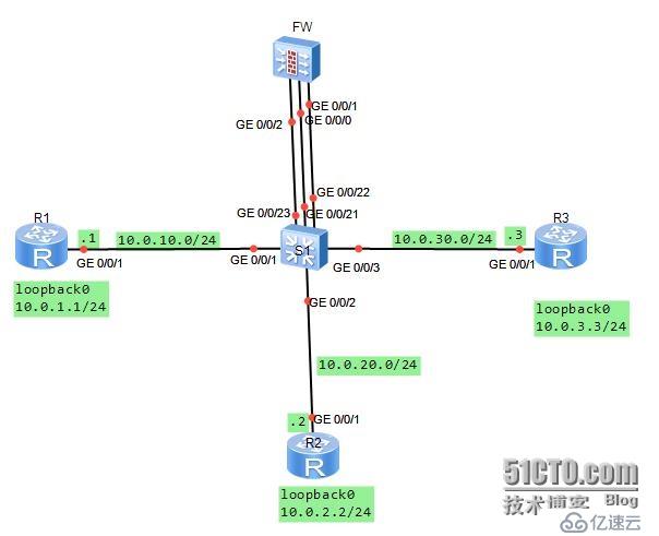
## 你是本公司的網路管理者。公司使用網路防火牆隔離成三個區域。現在要將DMZ區域中的一台伺服器(IP位址:10.0.3.3)提供的telnet服務發佈出去,對外公開的位址是10.0.10.20、24.並且內部網路Trust區域的用戶透過Easy-IP的方式訪問外部區域。其它方向的訪問被禁止。 在交換器上將G0/0/1與G0/0/21介面定義至vlan11,並將G0/0/2與G0/0/22介面定義至vlan12,且將G0/0/3與G0/0/23介面定義到vlan13.分別規劃了三個網段。
學
練習任務步驟一.
#基本設定與IP編址
# 先為三個路由器設定位址資訊。 [Huawei]sysname R1[R1]interface g0/0/1[R1-GigabitEthernet0/0/1]ip add 10.0.10.124#[R1-GigabitEthernet0/0/1]desc this portconnect to S1-G0/0/1[R1-GigabitEthernet0/0/1]interfaceloopback0[R1-LoopBack0]ip add 10.0.1.1 24[R1-LoopBack0]q[Huawei]sysname R2[R2]interface g0/0/1[ R2-GigabitEthernet0/0/1]ip add 10.0.20.224[R2-GigabitEthernet0/0/1]desc this portconnect to S1-G0/0/2#[R2-GigabitEthernet0/ 0/1]interfaceloopback0[R2-LoopBack0]ip add 10.0.2.2 24[R2-LoopBack0]q[Huawei]sysname R3[R3]interface g0/0/1[R3-GigabitEthernet0/0/1]ip add 10.0.30.324[R3-GigabitEthernet0/0/1]desc this portconnect 到 S1 -G0/0/3[R3-GigabitEthernet0/0/1]interfaceloopback0[R3-LoopBack0]ip add 10.0.3.3 24[R3-LoopBack0] q給防火牆設定位址時,G0/0/1設定10.0.20.254/24.[SRG]sysname FW
##13:06:03 2014/07 /08
[FW]interface g0/0/1
13:06:30 2014/07/08
[FW-GigabitEthernet0/0/1]ip add 10.0.20.25424
13:07:01 2014/07/08
[FW-GigabitEthernet0/0/1]desc this portconnect to S1-G0/0/22
# #13:07:52 2014/07/08
[FW-GigabitEthernet0/0/1]interface g0/0/0
13:08:23 2014/07/08
[FW-GigabitEthernet0/0/0]dis this
13:08:31 2014/07/08
##interface GigabitEthernet0/0/0
alias GE0/MGMT
ipaddress 192.168.0.1 255.255.255.0
# dhcpselect interface
dh#server gateway-
dhcpselect interface dh#server gateway-dhcpselect interface
dh##168.
#return
[FW-GigabitEthernet0/0/0]undo ip add
13:08:42 2014/07/08
Info: The DHCP server configuration on thisinterface will be deleted.
[FW-GigabitEthernet0/0/0]display this
13:08:46 2014/07/08
##interface GigabitEthernet0/0/0
alias GE0/MGMT
#return
[FW-GigabitEthernet0/0/0 ]ip add 10.0.10.25424
13:09:29 2014/07/08
[FW-GigabitEthernet0/0/0]desc this portconnect to S1-G0/0/21
13:10:05 2014/07/08
[FW-GigabitEthernet0/0/0]interface G0/0/2
13:10:15 2014/07/ 08
[FW-GigabitEthernet0/0/2]ip add 10.0.30.25424
13:10:28 2014/07/08
[FW-GigabitEthernet0/0/ 2]desc this portconnect to S1-G0/0/23
13:10:53 2014/07/08
[FW-GigabitEthernet0/0/2]q
# #交換器上需要依照需求定義vlan
[Huawei]sysname S1
[S1]vlan batch 11 to 13
Info: This operation may take a fewseconds. Please wait for a moment...done.
[S1]interface g0/0/1
[S1-GigabitEthernet0/0/1]port link-typeaccess
[S1 -GigabitEthernet0/0/1]port default vlan11
[S1]interface g0/0/2
[S1-GigabitEthernet0/0/2]port link-typeaccess
# [S1-GigabitEthernet0/0/2]port default vlan12
[S1-GigabitEthernet0/0/2]interface g0/0/3[S1-GigabitEthernet0/0/3]port link -typeaccess[S1-GigabitEthernet0/0/3]port default vlan13
###[S1-GigabitEthernet0/0/3]interface g0/0/21######[S1- GigabitEthernet0/0/21]port link-typeaccess######[S1-GigabitEthernet0/0/21]port default vlan11#########[S1-GigabitEthernet0/0/21]port default vlan11#######[S1-GigabitEthernet0/0/21]interface g0/0/22#[S1-GigabitEthernet0/0/21]interface g0/0/22# #####[S1-GigabitEthernet0/0/22]port link-typeaccess######[S1-GigabitEthernet0/0/22]port default vlan12######[S1-GigabitEthernet0/0/22 ]interface g0/0/23######[S1-GigabitEthernet0/0/23]port link-typeaccess######[S1-GigabitEthernet0/0/23]port default vlan13####### ###步驟二.######將介面設定到安全區域#######防火牆預設有四個區域,分別為「local」、「trust"、「untrust」、「dmz」。
實驗中我們使用「trust」、'untrust"、「dmz」三個區域。將G0/0/0配置到untrust區域,將G0/0/0/2配置到dmz區域,將G0/0/0/1配置到trust區域。
[FW]firewall zone trust
13:45:31 2014/07/08
[FW- zone-trust]dis this
13:45:35 2014/07/08
firewall zone trust
# setpriority 85
# addinterface GigabitEthernet0/0/0
#return
[FW-zone-trust]undo add inter
#[FW-zone-trust ]undo add interface g0/0/0
13:46:01 2014/07/08
[FW-zone-trust]add interface g0/0/1
13:46:22 2014/07/08
[FW-zone-trust]firewall zone untrust
[FW-zone-untrust]add interface g0/0/0
#[FW-zone-untrust]add interface g0/0/0
13:47:24 2014/07/08
[[FW-zone-untrust]firewall zone dmz
13:48:06 2014/07/08
[FW-zone-dmz]add interface g0/0/2
13:48:13 2014/07/08
[FW-zone-dmz]q
# 預設情況下,防火牆並不允許出local區域外的其它區域之間進行通訊。為了確保配置的準確性,我們將預設的防火牆過濾規則配置為允許所有區域之間的通訊。配置完成後在FW設備上測試連結性。
[FW]firewall packet-filter default permitall
13:51:19 2014/07/08
Warning:Setting the default packetfiltering to permit poses security risks. You
are advised to configure the securitypolicy based on the actual data flows. Are
you sure you want to continue. ##[FW]ping -c 1 10.0.10.1
13:51:56 2014/07/08
PING 10.0.10.1: 56 data bytes,press CTRL_C to break
Reply from 10.0.10.1: bytes=56 Sequence=1 ttl=255 time=90 ms
---10.0.10.1 ping statistics ---
pack
1packet(s) received
0.00% packet loss
round-trip min/avg/max = 90/90/90 ms
[FW ]ping -c 1 10.0.20.2
13:52:08 2014/07/08
PING 10.0.20.2: 56 data bytes,press CTRL_C to breakbreak
" from 10.0.20.2: bytes=56 Sequence=1 ttl=255 time=400 ms ---10.0.20.2 ping statistics --- 1packet(s) transmitted# 1packet(s) received
0.00% packet loss
round-trip min/avg/max = 400/400/400 ms
[FW]ping -c 1 10.0.30.3
13:52:18 2014/07/08
PING 10.0.30.3: 56 data bytes,press CTRL_C to break
o##Re : bytes=56 Sequence=1 ttl=255 time=410 ms ---10.0.30.3 ping statistics --- 1packet(s) transmitted# . s) received
0.00% packet loss
round-trip min/avg/max = 410/410/410 ms
步驟三.設定靜態路由,實現網路的靜態設定連結性
在R2和R3上設定預設路由,並在FW上配置明確的靜態路由,實現三個loopback0介面之間的通訊。由於R1是網路設備,無需了解內部和DMZ區域的私人網路訊息,因此無需定義預設路由。
[R2]ip route-static 0.0.0.0 0 10.0.20.254
[R3]ip route-static 0.0.0.0 0 10.0.30.254
##[FW]ip
#########################################! route-static 10.0.1.0 24 10.0.10.1######13:58:26 2014/07/08#######[FW]ip route-static 10.0.2.0 24 10.0.20. ##13:58:40 2014/07/08######[FW]ip route-static 10.0.3.0 24 10.0.30.3######13:58:52 2014/07/08## #### 在防火牆上測試與10.0.1.0、10.0.2.0、10.0.3.0之間的連結性。 ######[FW]ping -c 1 10.0.1.1#####14:00:18 2014/07/08###### PING 10.0.1.1: 56 data bytes,press CTRL_C to break###### Reply from 10.0.1.1: bytes=56 Sequence=1 ttl=255 time=80 ms###### ---10.0.1.1 ping statistics ---######卷(s) transmitted###### 1packet(s) received###### 0.00% packet loss####### round-trip min/avg/max = 80/#### round-trip min/avg/max = 80/10/# round-trip min/avg/max = 80/80/# ## ##[FW]ping -c 1 10.0.2.2######14:00:25 2014/07/08###### PING 10.0.2.2: 56 data bytes,press CTRL_C 至 break### ### Reply from 10.0.2.2: bytes=56 Sequence=1 ttl=255 time=170 ms###### ---10.0.2.2 ping statistics ---##### ###### 1packet(s) received###### 0.00% packet loss###### round-trip min/avg/max = 170/170/170 ms####FW[FW ]ping -c 1 10.0.3.3######14:00:29 2014/07/08###PING 10.0.3.3: 56 data bytes,press CTRL_C to break
Reply from 10.0.3.3: bytes=56 Sequence=1 ttl=255 time=110 ms#-#> 10.0.3.3 ping statistics ---
## 1packet(s) transmitted 1packet(s) received 0.00% packet(s) received 0.00% packet loss#dnound /avg/max = 110/110/110 ms 在目前設定下,所有區域之間可通訊,且不被檢查。由於NAT尚未被定義,內部和DMZ區域無法與外部區域相互存取。步驟四.
設定區域間的安全過濾器 配置從Trust區域的部分網段10.0.2.3發往Untrust區域的資料包被放行。 Telnet request sent from the Untrust zone to DMZ target server 10.0.3.3 was allowed to pass.。
[FW]firewall session link-state check[FW]policy interzone trust untrust outbound[FW-policy-interzone-trust-untrust-outbound]policy014:06:57 2014/07/08[FW-policy-interzone-trust-untrust-outbound-0]policysource 10.0.2.0 0.0.0.255#14 :07:18 2014/07/08[FW-policy-interzone-trust-untrust-outbound-0]actionpermit#14:07:31 2014/07/08[FW-policy-interzone-trust-untrust-outbound-0]q14:07:40 2014/07/08#[FW-policy-interzone-trust- untrust-outbound]q14:07:40 2014/07/08]policy interzone dmz untrust inbound#14:09:01 2014/07/08[FW-policy-interzone-dmz-untrust-inbound]policy014:09:08 2014/07/08[FW-policy-interzone-dmz- untrust-inbound-0]policydestination 10.0.3.3 014:09:37 2014/07/08#[FW-policy-interzone-dmz-untrust-inbound-0]policyservice service -set telnet[FW-policy-interzone-dmz-untrust-inbound-0]actionpermit14:09:55 2014/07/08[FW- policy-interzone-dmz-untrust-inbound-0]q14:09:55 2014/07/08
步驟五
. 配置Easy-Ip,實作Trust區域到Untrust##區域的訪問。 設定使用Easy-IP,進行NAT來源位址轉換。並且將NAT與介面進行綁定。 [FW-nat-policy-interzone-trust-untrust-outbound]policy0
14:14:00 2014/07/08
[FW-nat-policy -interzone-trust-untrust-outbound-0]policysource 10.0.2.0 0.0.0.2
55
14:14:26 2014/07/08
[FW- nat-policy-interzone-trust-untrust-outbound-0]actionsource-nat
14:14:37 2014/07/08
#[FW-nat-policy-interzone-trust- untrust-outbound-0]easy-ipg0/0/0
14:14:51 2014/07/08
[FW-nat-policy-interzone-trust-untrust-outbound- 0]q
配置完成後,以驗證Trust區域與Untrust區域之間的存取是否正常。
PING 10.0.1.1: 56 data bytes,press CTRL_C to break
Request time out#c#Re out
Request time out
Request time out
Request time out
---10.0.1.1 ping statistics ---
## ---10.0.1.1 ping statistics ---##-
5packet(s) transmitted
0packet(s) received
## 100.00% packet loss在R3上開啟Telnet功能,在R1上測試,測試時需注意,對外發佈的位址為10.0.10.20,所以R1對10.0.3.3存取時,存取的目標位址為10.0.10.20。
[R3]user-interface vty 0 4
[R3-ui-vty0-4]authentication-mode password
Please configure the login password(maximum length 16) :16
[R3-ui-vty0-4]set authentication password ?
cipher Set the password withcipher text
[R3-ui-vty0-4]set authentication passwordcip
[R3-ui-vty0-4]set authentication passwordcipher Huawei
#[R3-ui-vty0-4]user privilege level 3
#[R3-ui-vty0-4]user privilege level 3#[R3-ui-vty0-4]user privilege level 3
#[R3-uity0-4]user privilege level 3#[R3-uity0-4]user privilege level 3
#[R3-uity0-4]user privilege level 3##[ vty0-4]q
Press CTRL_] to quit telnet mode
Trying 10.0.10.20 ...
Connected to 10.0.10.20 ...
Login authentication
###Password:######以上是USG防火牆中的NAT配置的詳細內容。更多資訊請關注PHP中文網其他相關文章!

熱AI工具

Undresser.AI Undress
人工智慧驅動的應用程序,用於創建逼真的裸體照片

AI Clothes Remover
用於從照片中去除衣服的線上人工智慧工具。

Undress AI Tool
免費脫衣圖片

Clothoff.io
AI脫衣器

Video Face Swap
使用我們完全免費的人工智慧換臉工具,輕鬆在任何影片中換臉!

熱門文章

熱工具

記事本++7.3.1
好用且免費的程式碼編輯器

SublimeText3漢化版
中文版,非常好用

禪工作室 13.0.1
強大的PHP整合開發環境

Dreamweaver CS6
視覺化網頁開發工具

SublimeText3 Mac版
神級程式碼編輯軟體(SublimeText3)
 如何修復OneDrive中的'錯誤:0x80070185,雲端操作不成功”
May 16, 2023 pm 04:26 PM
OneDrive是微軟提供的熱門的雲端儲存應用程式。我們大多數人使用OneDrive來儲存我們的文件,資料夾,文件等。但一些用戶抱怨說,當他們嘗試存取OneDrive上的共享檔案時,它會給出錯誤,指出「錯誤:0x80070185,雲端操作不成功」。因此,他們無法在OneDrive上執行任何操作,例如複製文件,貼上,下載共享文件等。如今,有必要在我們的日常工作中使用這些操作。此錯誤可以輕鬆解決,為此,我們有一些方法可以應用並嘗試解決問題。讓我們開始吧!方法1–登出並重新登入OneDrive應用程式步驟
 NAT Boost與遊戲的Qos;哪個比較好?
Feb 19, 2024 pm 07:00 PM
在當下幾乎所有遊戲都在線上的情況下,忽視家庭網路的最佳化是不可取的。幾乎所有路由器都配備了NATBoost和QoS功能,旨在提升使用者的遊戲體驗。本文將探討NATBoost和QoS的定義、優點和缺點。 NATBoost與遊戲的Qos;哪個比較好? NATBoost,又稱網路位址轉換Boost,是一種內建於路由器的功能,可提升其效能。對於遊戲而言尤其重要,因為它有助於減少網路延遲,即遊戲設備和伺服器之間資料傳輸的時間。透過優化路由器內的資料處理方式,NATBoost實現了更快的資料處理速度和更低的延遲,從而改
 win11防火牆進階設定灰色解決方法
Dec 24, 2023 pm 07:53 PM
很多朋友在設定防火牆的時候,發現自己的win11防火牆高級設定灰色了,無法點擊。這可能是由於沒有添加控制單元導致的,也可能是沒有透過正確的方法打開高級設置,下面一起來看看怎麼解決吧。 win11防火牆進階設定灰色方法一:1、先點選下方開始選單,在上方搜尋並開啟「控制台」2、接著開啟其中的「Windowsdefender防火牆」3、進入後,在左邊欄就可以開啟「進階設定」了。方法二:1、如果上面方法也打不開,可以右鍵“開始選單”,打開“運行”2、然後輸入“mmc”回車確定打開。 3.打開後,點選左上
 如果 Grammarly 無法在 Windows 10 瀏覽器上執行的 8 個重大修復
May 05, 2023 pm 02:16 PM
如果您在Windows10或11PC上遇到語法問題,本文將協助您解決此問題。 Grammarly是最受歡迎的打字助理之一,用於修復語法、拼字、清晰度等。它已經成為寫作專業人士必不可少的一部分。但是,如果它不能正常工作,它可能是一個非常令人沮喪的體驗。許多Windows使用者報告說此工具在他們的電腦上運作不佳。我們做了深入的分析,找到了這個問題的原因和解決方案。為什麼Grammarly無法在我的PC上運作?由於幾個常見原因,PC上的Grammarly可能無法正常運作。它包括以下內
 修復:Windows 11 防火牆阻止印表機
May 01, 2023 pm 08:28 PM
防火牆監控網路流量,並可以阻止某些程式和硬體的網路連線。 Windows11包含自己的WindowsDefender防火牆,可能會阻止印表機存取Web。因此,當防火牆封鎖時,受影響的使用者無法使用他們的Brother印表機。請記住,此問題也會影響其他品牌,但今天我們將向您展示如何解決該問題。為什麼我的Brother印表機被防火牆封鎖了?此問題有多種原因,您很可能需要先打開某些端口,然後您的印表機才能存取網路。印表機軟體也可能導致問題,因此請務必更新它以及您的印表機驅動程式。繼續閱讀以了解如
 如何在 Alpine Linux 上啟用或停用防火牆?
Feb 21, 2024 pm 12:45 PM
在AlpineLinux上,你可以使用iptables工具來設定和管理防火牆規則。以下是在AlpineLinux上啟用或停用防火牆的基本步驟:檢查防火牆狀態:sudoiptables-L如果輸出結果中顯示有規則(例如,有一些INPUT、OUTPUT或FORWARD規則),則表示防火牆已啟用。如果輸出結果為空,則表示防火牆目前處於停用狀態。啟用防火牆:sudoiptables-PINPUTACCEPTsudoiptables-POUTPUTACCEPTsudoiptables-PFORWARDAC
 如何修復UFW狀態在Linux中顯示為非活動
Mar 20, 2024 pm 01:50 PM
UFW,又稱Uncomplex防火牆,被許多Linux發行版採用作為其防火牆系統。 UFW的設計讓新手使用者能夠輕鬆透過命令列介面和圖形使用者介面來管理防火牆設定。 UFW防火牆是一種能根據設定規則監控網路流量的系統,以保護網路免受網路嗅探和其他攻擊的影響。如果您在Linux系統上安裝了UFW但其狀態顯示為非活動狀態,可能有多種原因。在這篇指南中,我將分享如何解決Linux系統上UFW防火牆處於非活動狀態的問題。為什麼UFW在Linux上顯示不活動狀態為什麼UFW在Linux上預設不活動如何在Linu
 如何移除Win10桌面圖示上的防火牆標誌?
Jan 01, 2024 pm 12:21 PM
很多使用win10系統的小伙伴發現,電腦桌面的圖標上有防火牆的標誌,這是什麼情況呢?這讓很多有強迫症的小伙伴特別難受,其實我們只要打開控制面板,在用戶帳戶中的“更改使用者帳號控制設定」變更就可以解決了,具體的教學一起來看看吧。 win10桌面圖示有防火牆標誌怎麼取消1、首先,透過滑鼠右鍵點選電腦開機畫面旁的開始功能表按鈕,然後從彈出的選單中選取控制面板功能。 2.緊接著選擇其中的「使用者帳戶」選項,從接下來出現的新介面中選擇「更改使用者帳戶控制設定」此項目。 3.調整視窗中的滑桿至底部之後,點選確認退出


